- 您现在的位置:买卖IC网 > PDF目录98183 > TC90A80N Y/C SEPARATOR IC, PDIP28 PDF资料下载
参数资料
| 型号: | TC90A80N |
| 元件分类: | 信号分离 |
| 英文描述: | Y/C SEPARATOR IC, PDIP28 |
| 封装: | 0.400 INCH, 1.78 MM PITCH, PLASTIC, SDIP-28 |
| 文件页数: | 21/23页 |
| 文件大小: | 378K |
| 代理商: | TC90A80N |
TC90A80N/F
2002-12-04
7
IC Control Specifications
Functions and characteristics of this IC are set using the I2C bus.
The data transfer format conforms to the Philips I2C bus format.
When reset signal is applied, the following DATA bits are all cleared to 0.
Data transfer format
S
Slave address (8 bits)
A
DATA1
A
DATA2
A
DATA3
A
DATA4
A
P
Slave address: B4H S: Start condition, A: Acknowledgement, P: Stop condition
Outline of I2C bus format
I2C bus transfers data between ICs using two lines: data (SDA) and clock (SCL).
The I2C bus starts according to the start condition and ends according to the stop condition.
The start condition is satisfied if SDA changes from High to Low when SCL is High.
The stop condition is satisfied if SDA changes from Low to High when SCL is High.
The length of data to be transferred is 8 bits. Data are transferred via the SDA line. An acknowledge (ACK) bit is required after a
data byte. The bus line must be pulled up to the power supply level using a resistor. When SCL is High, data must not be
changed.
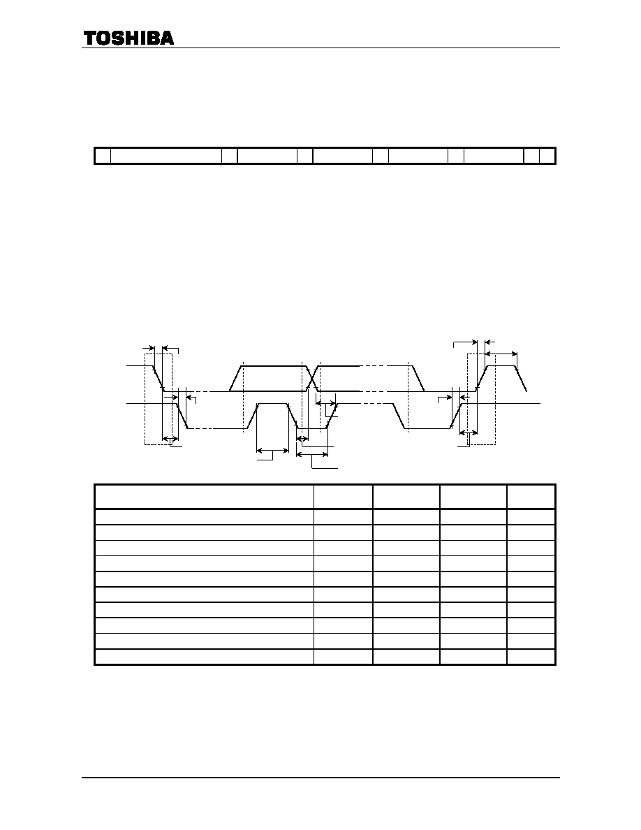
I2C bus control signal timing
Characteristics
Symbol
Min
Max
Unit
SCL clock frequency
fSCL
0
100
kHz
Hold time to satisfy start condition
tHD; STA
4.0
―
s
SCL clock Low period
tLOW
4.7
―
s
SCL clock High period
tHIGH
4.0
―
s
Data hold time
tHD; DAT
0
3.45
s
Data setup time
tSU; DAT
250
―
ns
SDA/SCL signal rise time
tr
―
1000
ns
SDA/SCL signal fall time
tf
―
300
ns
Stop condition setup time
tSU; STO
4.0
―
s
Bus free time between stop and start conditions
tBUF
4.7
―
s
Purchase of TOSHIBA I2C components conveys a license under the Philips I2C Patent Rights to use these components in an I2C
system, provided that the system conforms to the I2C Standard Specification as defined by Philips.
Date
Clock
Start Condition
tHD; STA
tLOW
tHIGH
tSU; DAT
tHD; DAT
tSU; STO
tBUF
tr
tf
Stop Condition
Don’t change the data while clock is in High level.
相关PDF资料 |
PDF描述 |
|---|---|
| TC90A92AFG | SPECIALTY CONSUMER CIRCUIT, PQFP100 |
| TC9163AN | SPECIALTY ANALOG CIRCUIT, PDIP28 |
| TC9164AF | SPECIALTY ANALOG CIRCUIT, PDSO28 |
| TC9162AF | SPECIALTY ANALOG CIRCUIT, PDSO28 |
| TC9181P | PLL FREQUENCY SYNTHESIZER, 10 MHz, PDIP18 |
相关代理商/技术参数 |
参数描述 |
|---|---|
| TC90A92AFG | 制造商:TOSHIBA 制造商全称:Toshiba Semiconductor 功能描述:3D comb & Video Decoder |
| TC90L01NG | 制造商:TOSHIBA 制造商全称:Toshiba Semiconductor 功能描述:Audio/Video Switching IC for TVs |
| TC9106BP | 制造商:TOSHIBA 制造商全称:Toshiba Semiconductor 功能描述:TC9106BP CB TRANSCEIVER PLL FREQUENCY SYNTHESIZER |
| TC9109BP | 制造商:TOSHIBA 制造商全称:Toshiba Semiconductor 功能描述:TC9109BP CB TRANSCEIVER PLL FREQUENCY SYNTHESIZER |
| TC911 | 制造商:TELCOM 制造商全称:TelCom Semiconductor, Inc 功能描述:AUTO-ZEROED OPERATIONAL AMPLIFIERS |
发布紧急采购,3分钟左右您将得到回复。