- 您现在的位置:买卖IC网 > PDF目录98183 > TC90A80N Y/C SEPARATOR IC, PDIP28 PDF资料下载
参数资料
| 型号: | TC90A80N |
| 元件分类: | 信号分离 |
| 英文描述: | Y/C SEPARATOR IC, PDIP28 |
| 封装: | 0.400 INCH, 1.78 MM PITCH, PLASTIC, SDIP-28 |
| 文件页数: | 3/23页 |
| 文件大小: | 378K |
| 代理商: | TC90A80N |
TC90A80N/F
2002-12-04
11
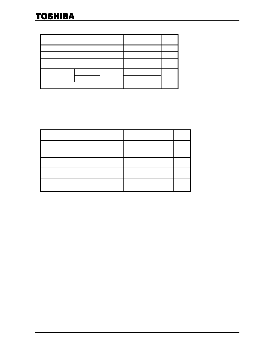
Maximum Rating (Ta = 25°C)
Characteristics
Symbol
Rating
Unit
Supply voltage
VDD
VSS + 6.0
V
Input voltage
VIN
VSS 0.3 to VDD + 0.3
V
Potential difference between power
supply pins
(Note 2)
VDG
0.4
V
TC90A80N
900
Power dissipation
(Note 3)
TC90A80F
PD
600
mW
Storage temperature
Tstg
-55 to +125
°C
Note 2: Connect pin 3 to pin 23. The potential difference among all power supply pins, 3 (23), 12, 13, and 20, must
not exceed 0.4 V.
The potential difference among VSS pins 5, 10, 21, and 26 must not exceed 0.01 V.
Note 3: Ta = 75
°C for TC90A80F mounted on a PCB (70 mm × 70 mm × 1.6 mm)
Recommended Operating Conditions
Characteristics
Symbol
Min
Typ.
Max
Unit
Supply voltage
VDD
4.75
5.00
5.25
V
Potential difference between pins 3
and 23
(Note 4)
VDG1
―
0
0.04
V
Potential difference among power
supply pins 3,12, 13, and 20
VDG2
―
0
0.15
V
Potential difference among VSS pins
5, 10, 21, and 26
VSG
―
0
0.01
V
Input voltage
VIN
0
―
VDD
V
Operating temperature
Topr
10
―
75
°C
Note 4: Since power supply pins 3 and 23 are connected in the IC, supply power to them at the same voltage.
If there is a large potential difference between the pins, a large current flows through the IC causing
degradation or damage due to heat stress.
Maximum ratings: A set of specified parameter values which must not be exceeded during operation, even for an
instant. If any of these limit values is exceeded during operation, it causes permanent damage to
the TC90A80N/F. Therefore, care must be exercised that the TC90A80N/F operates within the
specified ranges.
Recommended operating conditions: Minimum, typical and maximum values for key operating parameters such as
supply voltage, DC voltage and operating temperature. Ensuring that the
parameter values remain within these specified ranges during operation will
help to ensure that the integrity of the TC90A80N/F is not compromised. When
designing video equipment, be aware that the TC90A80N/F can function within
the recommended operating ranges.
相关PDF资料 |
PDF描述 |
|---|---|
| TC90A92AFG | SPECIALTY CONSUMER CIRCUIT, PQFP100 |
| TC9163AN | SPECIALTY ANALOG CIRCUIT, PDIP28 |
| TC9164AF | SPECIALTY ANALOG CIRCUIT, PDSO28 |
| TC9162AF | SPECIALTY ANALOG CIRCUIT, PDSO28 |
| TC9181P | PLL FREQUENCY SYNTHESIZER, 10 MHz, PDIP18 |
相关代理商/技术参数 |
参数描述 |
|---|---|
| TC90A92AFG | 制造商:TOSHIBA 制造商全称:Toshiba Semiconductor 功能描述:3D comb & Video Decoder |
| TC90L01NG | 制造商:TOSHIBA 制造商全称:Toshiba Semiconductor 功能描述:Audio/Video Switching IC for TVs |
| TC9106BP | 制造商:TOSHIBA 制造商全称:Toshiba Semiconductor 功能描述:TC9106BP CB TRANSCEIVER PLL FREQUENCY SYNTHESIZER |
| TC9109BP | 制造商:TOSHIBA 制造商全称:Toshiba Semiconductor 功能描述:TC9109BP CB TRANSCEIVER PLL FREQUENCY SYNTHESIZER |
| TC911 | 制造商:TELCOM 制造商全称:TelCom Semiconductor, Inc 功能描述:AUTO-ZEROED OPERATIONAL AMPLIFIERS |
发布紧急采购,3分钟左右您将得到回复。