- 您现在的位置:买卖IC网 > PDF目录98228 > THS7303PW (TEXAS INSTRUMENTS INC) 3 CHANNEL, VIDEO AMPLIFIER, PDSO20 PDF资料下载
参数资料
| 型号: | THS7303PW |
| 厂商: | TEXAS INSTRUMENTS INC |
| 元件分类: | 音频/视频放大 |
| 英文描述: | 3 CHANNEL, VIDEO AMPLIFIER, PDSO20 |
| 封装: | GREEN, PLASTIC, TSSOP-20 |
| 文件页数: | 22/60页 |
| 文件大小: | 1980K |
| 代理商: | THS7303PW |
第1页第2页第3页第4页第5页第6页第7页第8页第9页第10页第11页第12页第13页第14页第15页第16页第17页第18页第19页第20页第21页当前第22页第23页第24页第25页第26页第27页第28页第29页第30页第31页第32页第33页第34页第35页第36页第37页第38页第39页第40页第41页第42页第43页第44页第45页第46页第47页第48页第49页第50页第51页第52页第53页第54页第55页第56页第57页第58页第59页第60页
17
20
19
18
GND
16
CH.2 IN B
CH.3 IN B
15
I 2C-A0
SDA
VS+ 11
14
13
12
SCL
CH. 3 SAG
I 2C-A1
CH.1 IN B
CH.2 IN A
CH.3 IN A
CH.1 IN A
NC
CH.3 OUT
CH. 2 SAG
CH.2 OUT
CH. 1 SAG
CH.1 OUT
NC
DAC /
Encoder
(THS8200)
3.3V
1
2
3
4
5
6
7
8
9
10
G’
B’
R’
External
Input
75 W
0.1 F
m
0.01 F
m
100 F
m
0.1 F
m
0.1 F
m
R
G’
Out
B’
Out
R’
Out
+
+Vs
I C
Controller
2
ACSTC
DC+135mV
SLOS479B
– OCTOBER 2005 – REVISED MARCH 2011
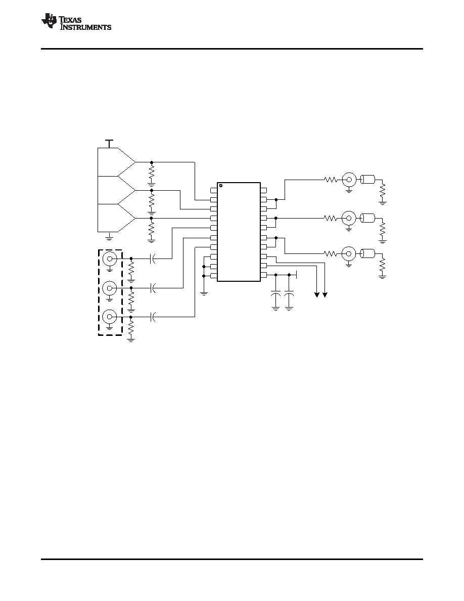
OUTPUT MODES OF OPERATION: DC COUPLED
The THS7303 incorporates a rail-to-rail output stage that can be used to drive the line directly without the need
for large ac-coupling capacitors. This is accomplished by connecting the output pin of each channel directly to
the SAG output pin of the corresponding channel as shown in Figure 64. This offers the best line tilt and field tilt
(or droop) performance since there is no ac coupling occurring. Keep in mind that if the input is ac coupled, then
the resulting tilt due to the input ac coupling is still seen on the output regardless of the output coupling. The
70-mA output current drive capability of the THS7303 is designed to drive two video lines simultaneously
(essentially a 75-
load), while keeping the output dynamic range as wide as possible.
Figure 64. Typical G
'B'R' (R'G'B') System With DC-Coupled Line Driving
One concern of dc coupling is if the line is terminated to ground. When the AC-Bias Input mode is selected, the
output of the THS7303 is at mid-rail. With two lines terminated to ground, this creates a dc current path to exist
that results in a slightly decreased high output voltage swing resulting in an increase in power dissipation of the
THS7303. While the THS7303 is designed to operate with a junction temperature of up to +125
°C, care must be
taken to ensure that the junction temperature does not exceed this level or else long-term reliability could suffer.
Although this configuration adds less than 10 mW of power dissipation per channel, the overall low power
dissipation of the THS7303 design minimizes potential thermal issues even when using the TSSOP package at
high ambient temperatures.
Note that the THS7303 can drive the line with dc coupling regardless of the input mode of operation. The only
requirement is to make sure the video line has proper termination in series with the output pin (typically 75
).
This helps isolate capacitive loading effects from the THS7303 output. Failure to isolate capacitive loads may
result in instabilities with the output buffer, potentially causing ringing or oscillations to appear. The stray
capacitance appearing directly at the THS7303 output pins should be kept below 25 pF for best performance.
When driving two video lines, each line should have its own 75-
source termination resistors to isolate the lines
from each other.
Copyright
2005–2011, Texas Instruments Incorporated
29
Product Folder Link(s): THS7303
相关PDF资料 |
PDF描述 |
|---|---|
| THS7303PWG4 | 3 CHANNEL, VIDEO AMPLIFIER, PDSO20 |
| THS7303PWRG4 | 3 CHANNEL, VIDEO AMPLIFIER, PDSO20 |
| THS7315DR | 3 CHANNEL, VIDEO AMPLIFIER, PDSO8 |
| THS7315D | 3 CHANNEL, VIDEO AMPLIFIER, PDSO8 |
| THS7315DG4 | 3 CHANNEL, VIDEO AMPLIFIER, PDSO8 |
相关代理商/技术参数 |
参数描述 |
|---|---|
| THS7303PWG4 | 功能描述:视频放大器 3-Ch Low Power Video RoHS:否 制造商:ON Semiconductor 通道数量:4 电源类型: 工作电源电压:3.3 V, 5 V 电源电流: 最小工作温度: 最大工作温度: 封装 / 箱体:TSSOP-14 封装:Reel |
| THS7303PWR | 功能描述:视频放大器 3-Ch Low Power Video RoHS:否 制造商:ON Semiconductor 通道数量:4 电源类型: 工作电源电压:3.3 V, 5 V 电源电流: 最小工作温度: 最大工作温度: 封装 / 箱体:TSSOP-14 封装:Reel |
| THS7303PWRG4 | 功能描述:视频放大器 3-Ch Low Power Video RoHS:否 制造商:ON Semiconductor 通道数量:4 电源类型: 工作电源电压:3.3 V, 5 V 电源电流: 最小工作温度: 最大工作温度: 封装 / 箱体:TSSOP-14 封装:Reel |
| THS730A A2 | 制造商:Tektronix Inc 功能描述:OSCILLOSCOPE DSO/DMM 200MHZ |
发布紧急采购,3分钟左右您将得到回复。