- 您现在的位置:买卖IC网 > PDF目录382605 > TLC32047IFN (Texas Instruments, Inc.) Wide-Band Analog Interface Circuit PDF资料下载
参数资料
| 型号: | TLC32047IFN |
| 厂商: | Texas Instruments, Inc. |
| 英文描述: | Wide-Band Analog Interface Circuit |
| 中文描述: | 宽带模拟接口电路 |
| 文件页数: | 39/61页 |
| 文件大小: | 303K |
| 代理商: | TLC32047IFN |
第1页第2页第3页第4页第5页第6页第7页第8页第9页第10页第11页第12页第13页第14页第15页第16页第17页第18页第19页第20页第21页第22页第23页第24页第25页第26页第27页第28页第29页第30页第31页第32页第33页第34页第35页第36页第37页第38页当前第39页第40页第41页第42页第43页第44页第45页第46页第47页第48页第49页第50页第51页第52页第53页第54页第55页第56页第57页第58页第59页第60页第61页
3–5
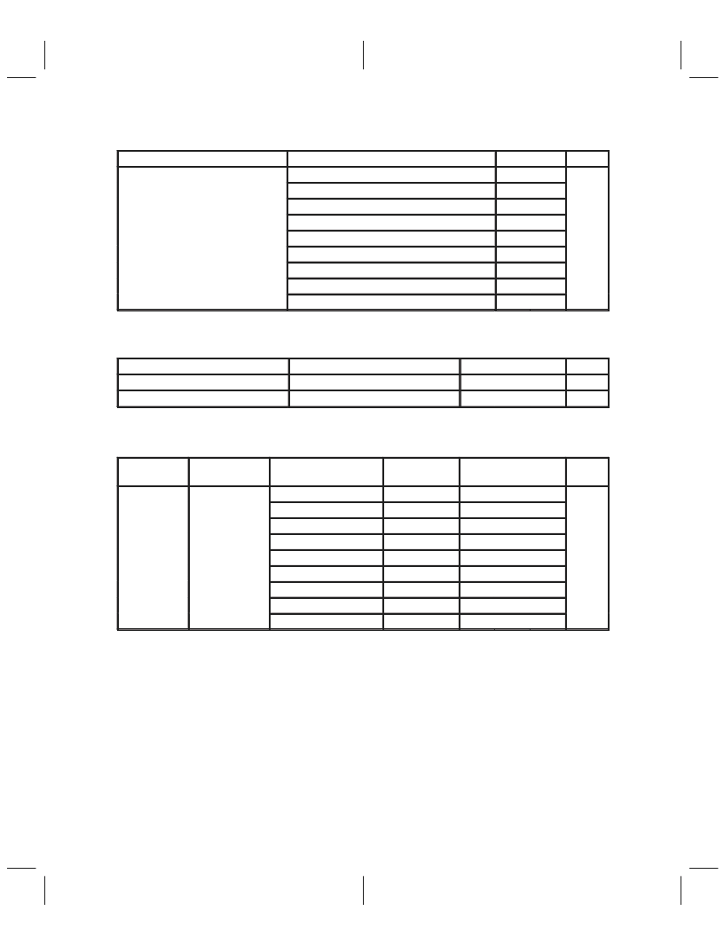
3.3.8
Transmit Channel Signal-to-Distortion Ratio (see Note 7)
PARAMETER
TEST CONDITIONS
VI = –6 dB to –0.1 dB
VI = –12 dB to –6 dB
VI = –18 dB to –12 dB
VI = –24 dB to –18 dB
VI = –30 dB to –24 dB
VI = –36 dB to –30 dB
VI = –42 dB to –36 dB
VI = –48 dB to –42 dB
VI = –54 dB to –48 dB
MIN
58
MAX
UNIT
58
56
50
D/A channel signal-to-distortion ratio
44
dB
38
32
26
20
NOTE 7: The test condition is a 1-kHz input signal with a 24-kHz conversion rate. The load impedance for the DAC is
600
. Input and output voltages are referred to Vref.
3.3.9
Receive and Transmit Gain and Dynamic Range (see Note 8)
PARAMETER
TEST CONDITIONS
MIN
TYP
±
0.05
±
0.05
MAX
±
0.25
±
0.25
UNIT
Transmit gain tracking error
VO = –48 dB to 0 dB signal range
VI = –48 dB to 0 dB signal range
dB
Receive gain tracking error
dB
NOTE 8: Gain tracking is relative to the absolute gain at 1 kHz and 0 dB (0 dB relative to Vref).
3.3.10
Receive Channel Band-Pass Filter Transfer Function, SCF f
clock
= 432 kHz,
Input (IN+ – IN–) is a
±
3-V Sine Wave
(see Note 9)
TEST
CONDITION
f
≤
150 Hz
f = 300 Hz
PARAMETER
FREQUENCY
ADJUSTMENT
MIN
TYP
MAX
UNIT
K1
×
0 dB
K1
×
–0.26 dB
K1
×
0 dB
K1
×
0 dB
K1
×
0 dB
K1
×
2.3 dB
K1
×
2.7 dB
K1
×
3.2 dB
K1
×
0 dB
–33
–29
–25
–4
–2
–1
f = 450 Hz to 9300 Hz
–0.25
0
0.25
Input signal
reference is 0 dB
f = 9300 Hz to 9900 Hz
–0.3
0
0.3
Filter gain
f = 9900 Hz to 10950 Hz
–0.5
0
0.5
dB
f = 11.4 kHz
–2
–0.5
f = 12 kHz
f
≥
13.2 kHz
f
≥
15 kHz
–16
–14
–40
–60
All typical values are at TA = 25
°
C.
The MIN, TYP, and MAX specifications are given for a 432-kHz SCF clock frequency. A slight error in the 432-kHz SCF
can result from inaccuracies in the MSTR CLK frequency, resulting from crystal frequency tolerances. If this frequency
error is less than 0.25%, the ADJUSTMENT ADDEND should be added to the MIN, TYP, and MAX specifications, where
K1 = 100
×
[(SCF frequency – 432 kHz)/432 kHz]. For errors greater than 0.25%, see Note 9.
NOTE 9: The filter gain outside of the pass band is measured with respect to the gain at 1 kHz. The filter gain within the
pass band is measured with respect to the average gain within the pass band. The pass bands are 450 Hz
to 10.95 kHz and 0 to 10.95 kHz for the band-pass and low-pass filters, respectively. For switched-capacitor
filter clocks at frequencies other than 432 kHz, the filter response is shifted by the ratio of switched-capacitor
filter clock frequency to 432 kHz.
相关PDF资料 |
PDF描述 |
|---|---|
| TLC32047C | Wide-Band Analog Interface Circuit |
| TLC32047I | Wide-Band Analog Interface Circuit |
| TLC320A545C | SMA (F) TO BNC (M) ADAPTERS |
| TLC320A545C-I | SMA (F) TO MCX (F) ADAPTERS |
| TLC320A545I | SMA (F) TO MCX (M) ADAPTERS |
相关代理商/技术参数 |
参数描述 |
|---|---|
| TLC32047IN | 制造商:TI 制造商全称:Texas Instruments 功能描述:Wide-Band Analog Interface Circuit |
| TLC3204CN | 制造商:Texas Instruments 功能描述: |
| TLC32071 | 制造商:TI 制造商全称:Texas Instruments 功能描述:HIGH-SPEED 8-BIT A/D AND D/A CONVERTER WITH 8-CHANNEL MULTIPLEXER |
| TLC320A545C | 制造商:TI 制造商全称:Texas Instruments 功能描述:Single Channel Data/Fax Codec |
| TLC320A545C-I | 制造商:TI 制造商全称:Texas Instruments 功能描述:Single Channel Data/Fax Codec |
发布紧急采购,3分钟左右您将得到回复。