- 您现在的位置:买卖IC网 > PDF目录98252 > TLV2556IPWR (TEXAS INSTRUMENTS INC) 11-CH 12-BIT SUCCESSIVE APPROXIMATION ADC, SERIAL ACCESS, PDSO20 PDF资料下载
参数资料
| 型号: | TLV2556IPWR |
| 厂商: | TEXAS INSTRUMENTS INC |
| 元件分类: | ADC |
| 英文描述: | 11-CH 12-BIT SUCCESSIVE APPROXIMATION ADC, SERIAL ACCESS, PDSO20 |
| 封装: | GREEN, PLASTIC, TSSOP-20 |
| 文件页数: | 20/37页 |
| 文件大小: | 729K |
| 代理商: | TLV2556IPWR |
第1页第2页第3页第4页第5页第6页第7页第8页第9页第10页第11页第12页第13页第14页第15页第16页第17页第18页第19页当前第20页第21页第22页第23页第24页第25页第26页第27页第28页第29页第30页第31页第32页第33页第34页第35页第36页第37页
TLV2556
SLAS355A – DECEMBER 2001 – REVISED SEPTEMBER 2002
27
www.ti.com
PRINCIPLES OF OPERATION
conversion cycle
A conversion cycle is started only after the I/O cycle is completed, which minimizes the influence of external
digital noise on the accuracy of the conversion. This cycle is transparent to the user because it is controlled by
an internal clock (oscillator). The total conversion time is equal to 13.5 OSC clocks plus a small delay (~25 ns)
to start the OSC. During the conversion period, the device performs a successive-approximation conversion
on the analog input voltage.
When programmed as EOC, pin 19 goes low at the start of the conversion cycle and goes high when the
conversion is complete and the output data register is latched. After EOC goes low, the analog input can be
changed without affecting the conversion result. Since the delay from the falling edge of the last I/O CLOCK to
the falling edge of EOC is fixed, any time-varying analog input signals can be digitized at a fixed rate without
introducing systematic harmonic distortion or noise due to timing uncertainty.
When programmed as INT, pin 19 goes low when the conversion is complete and the output data register is
latched. The next I/O CLOCK rising edge clears the INT output. The time from the last I/O CLOCK falling edge
to the falling INT edge is equivalent to the EOC delay mentioned above plus the maximum conversion time. INT
is cancelled by (or brought to high) by either the next CS falling edge or the next SCLK rising edge (when CS
is held low all of the time for multiple cycles). When CS is held low continuously (for multiple cycles) MSB output
occurs after the first rising edge of I/O CLOCK after EOC is inactive or the falling edge of INT.
power up and initialization
After power up, CS must be taken from high to low to begin an I/O cycle. INT/EOC pin is initially high, and both
configuration registers are set to all zeroes. The contents of the output data register are random, and the first
conversion result should be ignored. To initialize during operation, CS is taken high and is then returned low
to begin the next I/O cycle. The first conversion after the device has returned from the power-down state may
not read accurately due to internal device settling.
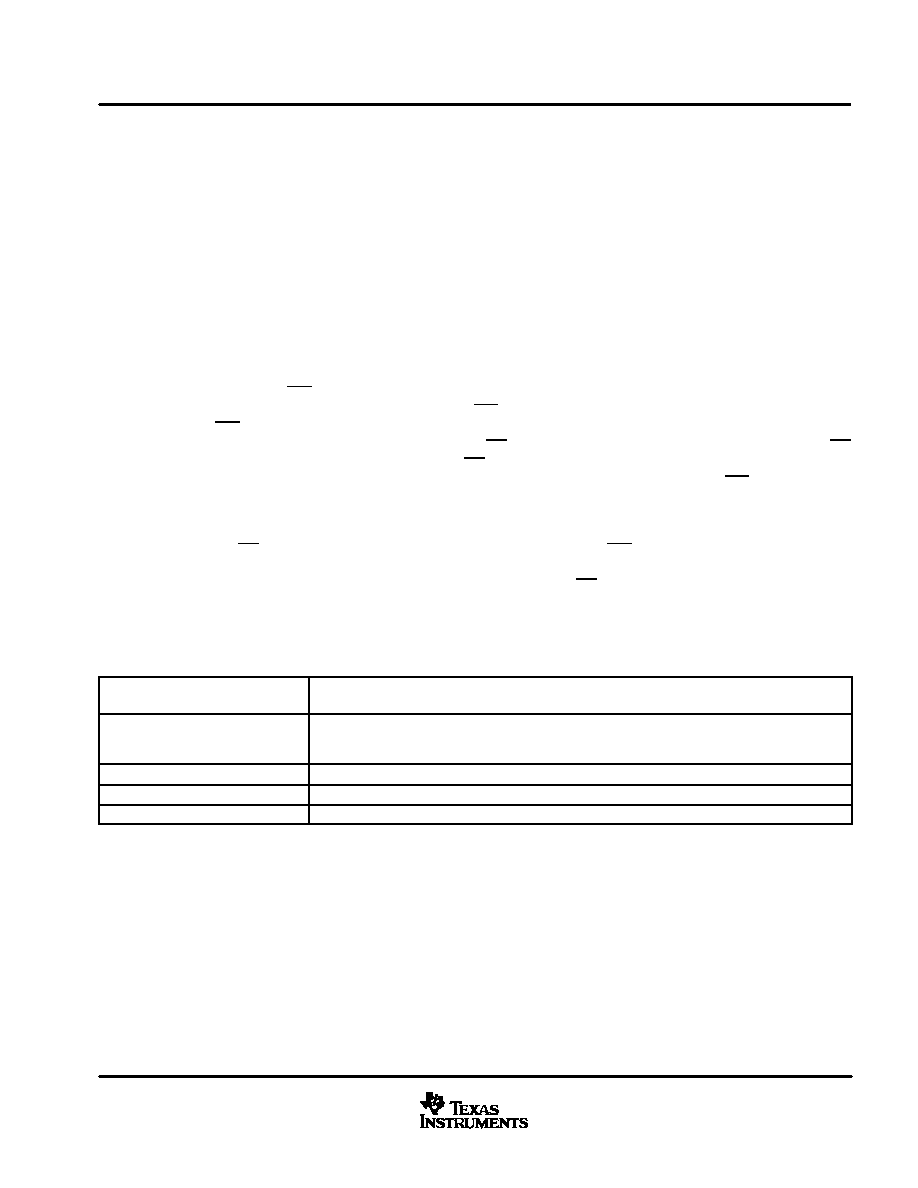
Table 1. Operational Terminology
Current (N) I/O cycle
The entire I/O CLOCK sequence that transfers address and control data into the data register and clocks
the digital result from the previous conversion from DATA OUT.
Current (N) conversion cycle
The conversion cycle starts immediately after the current I/O cycle. The end of the current I/O cycle is the
last clock falling edge in the I/O CLOCK sequence. The current conversion result is loaded into the out-
put register when conversion is complete.
Current (N) conversion result
The current conversion result is serially shifted out on the next I/O cycle.
Previous (N–1) conversion cycle
The conversion cycle just prior to the current I/O cycle
Next (N+1) I/O cycle
The I/O period that follows the current conversion cycle
Example:
In 12-bit mode, the result of the current conversion cycle is a 12-bit serial-data stream clocked out during the
next I/O cycle. The current I/O cycle must be exactly 12 bits long to maintain synchronization, even when this
corrupts the output data from the previous conversion. The current conversion is begun immediately after the
twelfth falling edge of the current I/O cycle.
相关PDF资料 |
PDF描述 |
|---|---|
| TLV2556IDW | 11-CH 12-BIT SUCCESSIVE APPROXIMATION ADC, SERIAL ACCESS, PDSO20 |
| TLV2556IPWG4 | 11-CH 12-BIT SUCCESSIVE APPROXIMATION ADC, SERIAL ACCESS, PDSO20 |
| TLV2556MPWREP | 11-CH 12-BIT SUCCESSIVE APPROXIMATION ADC, SERIAL ACCESS, PDSO20 |
| TLV2556MPWREPG4 | 11-CH 12-BIT SUCCESSIVE APPROXIMATION ADC, SERIAL ACCESS, PDSO20 |
| TLV320ADC3001IYZHT | 2-CH 16-BIT PROPRIETARY METHOD ADC, SERIAL ACCESS, PBGA16 |
相关代理商/技术参数 |
参数描述 |
|---|---|
| TLV2556IPWRG4 | 功能描述:模数转换器 - ADC 12-Bit 200 KSPS 11 Ch Lo-Pwr RoHS:否 制造商:Texas Instruments 通道数量:2 结构:Sigma-Delta 转换速率:125 SPs to 8 KSPs 分辨率:24 bit 输入类型:Differential 信噪比:107 dB 接口类型:SPI 工作电源电压:1.7 V to 3.6 V, 2.7 V to 5.25 V 最大工作温度:+ 85 C 安装风格:SMD/SMT 封装 / 箱体:VQFN-32 |
| TLV2556MPWREP | 功能描述:模数转换器 - ADC EP 12B,200KSPS,11Ch Low Pwr,Serial ADC RoHS:否 制造商:Texas Instruments 通道数量:2 结构:Sigma-Delta 转换速率:125 SPs to 8 KSPs 分辨率:24 bit 输入类型:Differential 信噪比:107 dB 接口类型:SPI 工作电源电压:1.7 V to 3.6 V, 2.7 V to 5.25 V 最大工作温度:+ 85 C 安装风格:SMD/SMT 封装 / 箱体:VQFN-32 |
| TLV2556MPWREPG4 | 功能描述:模数转换器 - ADC EP 12B,200KSPS,11Ch RoHS:否 制造商:Texas Instruments 通道数量:2 结构:Sigma-Delta 转换速率:125 SPs to 8 KSPs 分辨率:24 bit 输入类型:Differential 信噪比:107 dB 接口类型:SPI 工作电源电压:1.7 V to 3.6 V, 2.7 V to 5.25 V 最大工作温度:+ 85 C 安装风格:SMD/SMT 封装 / 箱体:VQFN-32 |
| TLV2620ID | 制造商:Rochester Electronics LLC 功能描述:- Bulk |
| TLV2620IDBVR | 功能描述:运算放大器 - 运放 800 uA/ch 11MHz RRO Lo-Vltg 1-Ch RoHS:否 制造商:STMicroelectronics 通道数量:4 共模抑制比(最小值):63 dB 输入补偿电压:1 mV 输入偏流(最大值):10 pA 工作电源电压:2.7 V to 5.5 V 安装风格:SMD/SMT 封装 / 箱体:QFN-16 转换速度:0.89 V/us 关闭:No 输出电流:55 mA 最大工作温度:+ 125 C 封装:Reel |
发布紧急采购,3分钟左右您将得到回复。