- 您现在的位置:买卖IC网 > PDF目录10958 > TLV320AIC31IRHBT (Texas Instruments)IC CODEC STEREO AUDIO 32-QFN PDF资料下载
参数资料
| 型号: | TLV320AIC31IRHBT |
| 厂商: | Texas Instruments |
| 文件页数: | 10/84页 |
| 文件大小: | 0K |
| 描述: | IC CODEC STEREO AUDIO 32-QFN |
| 标准包装: | 1 |
| 类型: | 立体声音频 |
| 数据接口: | PCM 音频接口 |
| 分辨率(位): | 24 b |
| ADC / DAC 数量: | 2 / 2 |
| 三角积分调变: | 是 |
| S/N 比,标准 ADC / DAC (db): | 92 / 100 |
| 动态范围,标准 ADC / DAC (db): | 92 / 100 |
| 电压 - 电源,模拟: | 2.7 V ~ 3.6 V |
| 电压 - 电源,数字: | 1.65 V ~ 1.95 V |
| 工作温度: | -40°C ~ 85°C |
| 安装类型: | 表面贴装 |
| 封装/外壳: | 32-VFQFN 裸露焊盘 |
| 供应商设备封装: | 32-QFN 裸露焊盘(5x5) |
| 包装: | 标准包装 |
| 配用: | 296-19476-ND - KIT EVAL/DEMO FOR TLV320AIC31 296-19475-ND - MODULE EVAL FOR TLV320AIC31 |
| 其它名称: | 296-19422-6 |
第1页第2页第3页第4页第5页第6页第7页第8页第9页当前第10页第11页第12页第13页第14页第15页第16页第17页第18页第19页第20页第21页第22页第23页第24页第25页第26页第27页第28页第29页第30页第31页第32页第33页第34页第35页第36页第37页第38页第39页第40页第41页第42页第43页第44页第45页第46页第47页第48页第49页第50页第51页第52页第53页第54页第55页第56页第57页第58页第59页第60页第61页第62页第63页第64页第65页第66页第67页第68页第69页第70页第71页第72页第73页第74页第75页第76页第77页第78页第79页第80页第81页第82页第83页第84页
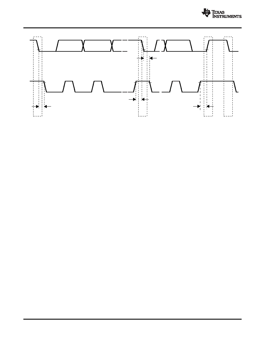
SDA
SCL
t
HD-STA
2.0
s
m
t
SU-STO
2.0
s
m
P
S
t
SU-STA
2.0
s
m
Sr
t
HD-STA
2.0
s
m
S
T0114-02
SLAS497C – AUGUST 2006 – REVISED DECEMBER 2008 ............................................................................................................................................. www.ti.com
Figure 15. I2C Interface Timing
Communication on the I2C bus always takes place between two devices, one acting as the master and the other
acting as the slave. Both masters and slaves can read and write, but slaves can only do so under the direction of
the master. Some I2C devices can act as masters or slaves, but the TLV320AIC31 can only act as a slave
device.
An I2C bus consists of two lines, SDA and SCL. SDA carries data; SCL provides the clock. All data are
transmitted across the I2C bus in groups of eight bits. To send a bit on the I2C bus, the SDA line is driven to the
appropriate level while SCL is LOW (a LOW on SDA indicates the bit is '0'; a HIGH indicates the bit is '1'). Once
the SDA line has settled, the SCL line is brought HIGH, then LOW. This pulse on SCL clocks the SDA bit into the
receiver shift register.
The I2C bus is bidirectional: the SDA line is used both for transmitting and receiving data. When a master reads
from a slave, the slave drives the data line; when a master sends to a slave, the master drives the data line.
Under most circumstances the master drives the clock line.
Most of the time the bus is idle; no communication takes place, and both lines are HIGH. When communication is
taking place, the bus is active. Only master devices can start a communication. They do this by causing a
START condition on the bus. Normally, the data line is only allowed to change state while the clock line is LOW.
If the data line changes state while the clock line is HIGH, it is either a START condition or its counterpart, a
STOP condition. A START condition is when the clock line is HIGH and the data line goes from HIGH to LOW. A
STOP condition is when the clock line is HIGH and the data line goes from LOW to HIGH.
After the master issues a START condition, it sends a byte that indicates which slave device it wants to
communicate with. This byte is called the address byte. Each device on an I2C bus has a unique 7-bit address to
which it responds. (Slaves can also have 10-bit addresses; see the I2C specification for details.) The master
sends an address in the address byte, together with a bit that indicates whether it wishes to read from or write to
the slave device.
Every byte transmitted on the I2C bus, whether it is address or data, is acknowledged with an acknowledge bit.
When a master has finished sending a byte (eight data bits) to a slave, it stops driving SDA and waits for the
slave to acknowledge the byte. The slave acknowledges the byte by pulling SDA LOW. The master then sends a
clock pulse to clock the acknowledge bit. Similarly, when a master has finished reading a byte, it pulls SDA LOW
to acknowledge this to the slave. It then sends a clock pulse to clock the bit.
A not-acknowledge is performed by simply leaving SDA HIGH during an acknowledge cycle. If a device is not
present on the bus, and the master attempts to address it, it will receive a not-acknowledge because no device is
present at that address to pull the line LOW.
When a master has finished communicating with a slave, it may issue a STOP condition. When a STOP
condition is issued, the bus becomes idle again. A master may also issue another START condition. When a
START condition is issued while the bus is active, it is called a repeated START condition.
18
Copyright 2006–2008, Texas Instruments Incorporated
Product Folder Link(s): TLV320AIC31
相关PDF资料 |
PDF描述 |
|---|---|
| VE-B43-IW-B1 | CONVERTER MOD DC/DC 24V 100W |
| VE-B1W-IW-B1 | CONVERTER MOD DC/DC 5.5V 100W |
| VE-B1V-IW-B1 | CONVERTER MOD DC/DC 5.8V 100W |
| VE-B0W-IX-B1 | CONVERTER MOD DC/DC 5.5V 75W |
| VE-B0L-IX-B1 | CONVERTER MOD DC/DC 28V 75W |
相关代理商/技术参数 |
参数描述 |
|---|---|
| TLV320AIC31IRHBT | 制造商:Texas Instruments 功能描述:IC CODEC STEREO AUDIO 32-VQFN |
| TLV320AIC31IRHBTG4 | 功能描述:接口—CODEC Lo-Pwr Ster Codec for Port Aud/Teleph RoHS:否 制造商:Texas Instruments 类型: 分辨率: 转换速率:48 kSPs 接口类型:I2C ADC 数量:2 DAC 数量:4 工作电源电压:1.8 V, 2.1 V, 2.3 V to 5.5 V 最大工作温度:+ 85 C 安装风格:SMD/SMT 封装 / 箱体:DSBGA-81 封装:Reel |
| TLV320AIC32 | 制造商:BB 制造商全称:BB 功能描述:LOW POWER STEREO AUDIO CODEC FOR PORTABLE AUDIO/TELEPHONY |
| TLV320AIC32_07 | 制造商:BB 制造商全称:BB 功能描述:LOW POWER STEREO AUDIO CODEC FOR PORTABLE AUDIO/TELEPHONY |
| TLV320AIC3204 | 制造商:TI 制造商全称:Texas Instruments 功能描述:Ultra Low Power Stereo Audio Codec |
发布紧急采购,3分钟左右您将得到回复。