参数资料
| 型号: | TMX320DM365BZCE |
| 厂商: | Texas Instruments |
| 文件页数: | 187/210页 |
| 文件大小: | 0K |
| 描述: | IC DIGITAL MEDIA SOC 338NFBGA |
| 标准包装: | 160 |
| 系列: | TMS320DM3x, DaVinci™ |
| 类型: | 数字媒体片内系统(DMSoC) |
| 接口: | HPI,I²C,McBSP,MMC,SD,SPI,UART,USB |
| 时钟速率: | 300MHz |
| 非易失内存: | ROM(16 kB) |
| 芯片上RAM: | 32kB |
| 电压 - 输入/输出: | 1.8V,3.3V |
| 电压 - 核心: | 1.35V |
| 工作温度: | 0°C ~ 85°C |
| 安装类型: | 表面贴装 |
| 封装/外壳: | 338-LFBGA |
| 供应商设备封装: | 338-NFBGA(13x13) |
| 包装: | 托盘 |
第1页第2页第3页第4页第5页第6页第7页第8页第9页第10页第11页第12页第13页第14页第15页第16页第17页第18页第19页第20页第21页第22页第23页第24页第25页第26页第27页第28页第29页第30页第31页第32页第33页第34页第35页第36页第37页第38页第39页第40页第41页第42页第43页第44页第45页第46页第47页第48页第49页第50页第51页第52页第53页第54页第55页第56页第57页第58页第59页第60页第61页第62页第63页第64页第65页第66页第67页第68页第69页第70页第71页第72页第73页第74页第75页第76页第77页第78页第79页第80页第81页第82页第83页第84页第85页第86页第87页第88页第89页第90页第91页第92页第93页第94页第95页第96页第97页第98页第99页第100页第101页第102页第103页第104页第105页第106页第107页第108页第109页第110页第111页第112页第113页第114页第115页第116页第117页第118页第119页第120页第121页第122页第123页第124页第125页第126页第127页第128页第129页第130页第131页第132页第133页第134页第135页第136页第137页第138页第139页第140页第141页第142页第143页第144页第145页第146页第147页第148页第149页第150页第151页第152页第153页第154页第155页第156页第157页第158页第159页第160页第161页第162页第163页第164页第165页第166页第167页第168页第169页第170页第171页第172页第173页第174页第175页第176页第177页第178页第179页第180页第181页第182页第183页第184页第185页第186页当前第187页第188页第189页第190页第191页第192页第193页第194页第195页第196页第197页第198页第199页第200页第201页第202页第203页第204页第205页第206页第207页第208页第209页第210页
SPRS457E
– MARCH 2009 – REVISED JUNE 2011
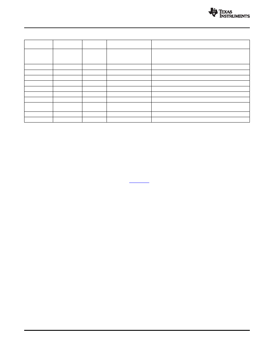
Table 6-1. Power Supplies (continued)
CUSTOMER
TOLERANCE
PACKAGE
DEVICE PLANE
DESCRIPTION
BOARD SUPPLY
PLANE
0 V
VSSA
PLL ground
Note: For proper device operation, keep separate from digital
ground VSS.
0 V
VSSA18_USB
USB ground
0 V
VSSA33_USB
3.3-V USB ground
0 V
VSSA33_VC
3.3-V Voice Codec Module ground
0 V
VSSA18_VC
1.8-V Voice Codec Module ground
0 V
VSSA_ADC
Analog-to-digital converter (ADC) ground
0 V
VSSA18_DAC
1.8-V DAC ground
0 V
VSSA12_DAC
1.2-V DAC ground
VDD18_DDR*0.5
DDR_VREF
DRR reference voltage
(VDDS divided by 2, through board resistors)
0.5V
±5%
VREF
DAC reference voltage
5.25V
USB_VBUS
VBUS
6.4
Power-Supply Sequencing
In order to ensure device reliability, the device requires the following power supply power-on and
power-off sequences. See Section 5.2, Recommended Operating Conditions, for a description of the
power supplies.
The following power sequences are recommended to prevent damage to the device.
The PRTCSS core must always be powered-on and powered-off regardless of whether the PRTCSS
feature is used.
If the PRTCSS sequencer is to be used in any PRTCSS modes, please refer to the TMS320DM36x
PRTCSS User's Guide (literature number SPRUFJ0) for more details on the differences to the power
sequence.
6.4.1
Simple Power-On and Power-Off Method
The following steps must be followed in sequential order for the simple power-on method:
1. Power on the PRTCSS/ Main core (1.2-V or 1.35-V).
2. Power on the PRTCSS/Main I/O (1.8-V).
3. Power on the Main/Analog I/O (3.3-V).
Note for simple power-on: RESET must be low until all supplies are ramped up.
The following steps should be followed for the simple power-off method:
1. Power off the Main/Analog I/O (3.3-V).
2. Power off the PRTCSS/Main I/O (1.8-V).
3. Power off the PRTCSS/Main core (1.2-V or 1.35-V).
Notes for simple power-off:
– If RESET is low, steps 2 and 3 may be performed simultaneously.
– If RESET is not low, these steps must be followed sequentially.
6.4.2
Restricted Power-On and Power-Off Method
The following steps should be followed for the restricted power-on method:
1. Power on the PRTCSS/ Main core (1.2-V or 1.35-V).
2. Power on the PRTCSS/Main I/O (1.8-V).
3. Power on the Main/Analog I/O (3.3-V).
Notes for restricted power-on:
78
Peripheral Information and Electrical Specifications
Copyright
2009–2011, Texas Instruments Incorporated
Product Folder Link(s): TMS320DM365
相关PDF资料 |
PDF描述 |
|---|---|
| TMX320F28069UPFPA | IC MCU 32BIT 128KB FLASH 80HTQFP |
| TPS2371PWRG4 | IC PWR INTRFCE SW FOR POE 8TSSOP |
| TS3A24157RSERG4 | IC SWITCH DUAL SPDT 10UQFN |
| TS5A3159MDBVREP | IC SWITCH SPDT SOT23-6 |
| TS87C51RB2-MCB | IC MCU 8BIT 16K OTP 40MHZ 44PLCC |
相关代理商/技术参数 |
参数描述 |
|---|---|
| TMX320DM365BZCE40 | 制造商:Texas Instruments 功能描述:SOC MICROPROCESSOR 1.42V 338-PIN NFBGA - Trays |
| TMX320DM365ZCE21F | 制造商:TI 制造商全称:Texas Instruments 功能描述:Digital Media System-on-Chip (DMSoC) |
| TMX320DM365ZCE27F | 制造商:TI 制造商全称:Texas Instruments 功能描述:Digital Media System-on-Chip (DMSoC) |
| TMX320DM365ZCE30F | 制造商:TI 制造商全称:Texas Instruments 功能描述:Digital Media System-on-Chip (DMSoC) |
| TMX320DM365ZCED21F | 制造商:TI 制造商全称:Texas Instruments 功能描述:Digital Media System-on-Chip (DMSoC) |
发布紧急采购,3分钟左右您将得到回复。