- 您现在的位置:买卖IC网 > PDF目录98306 > TVP5150AZQCR (TEXAS INSTRUMENTS INC) COLOR SIGNAL DECODER, PBGA48 PDF资料下载
参数资料
| 型号: | TVP5150AZQCR |
| 厂商: | TEXAS INSTRUMENTS INC |
| 元件分类: | 颜色信号转换 |
| 英文描述: | COLOR SIGNAL DECODER, PBGA48 |
| 封装: | PLASTIC, BGA-48 |
| 文件页数: | 6/74页 |
| 文件大小: | 439K |
| 代理商: | TVP5150AZQCR |
第1页第2页第3页第4页第5页当前第6页第7页第8页第9页第10页第11页第12页第13页第14页第15页第16页第17页第18页第19页第20页第21页第22页第23页第24页第25页第26页第27页第28页第29页第30页第31页第32页第33页第34页第35页第36页第37页第38页第39页第40页第41页第42页第43页第44页第45页第46页第47页第48页第49页第50页第51页第52页第53页第54页第55页第56页第57页第58页第59页第60页第61页第62页第63页第64页第65页第66页第67页第68页第69页第70页第71页第72页第73页第74页
24
At powerup the host interface is required to program the VDP-configuration RAM (VDP-CRAM) contents with the
lookup table (see Section 2.20.58). This is done through port address C3h. Each read from or write to this address
will auto increment an internal counter to the next RAM location. To access the VDP-CRAM, the line mode registers
(D0hFCh) must be programmed with FFh to avoid a conflict with the internal microprocessor and the VDP in both
writing and reading. Full field mode must also be disabled.
Available VBI lines are from line 6 to line 27 of both field 1 and field 2. Each line can be any VBI mode.
Output data is available either through the VBI-FIFO (B0h) or through dedicated registers at 90hAFh, both of which
are available through the I2C port.
2.9
VBI FIFO and Ancillary Data in Video Stream
Sliced VBI data can be output as ancillary data in the video stream in the ITU-R BT.656 mode. VBI data is output during
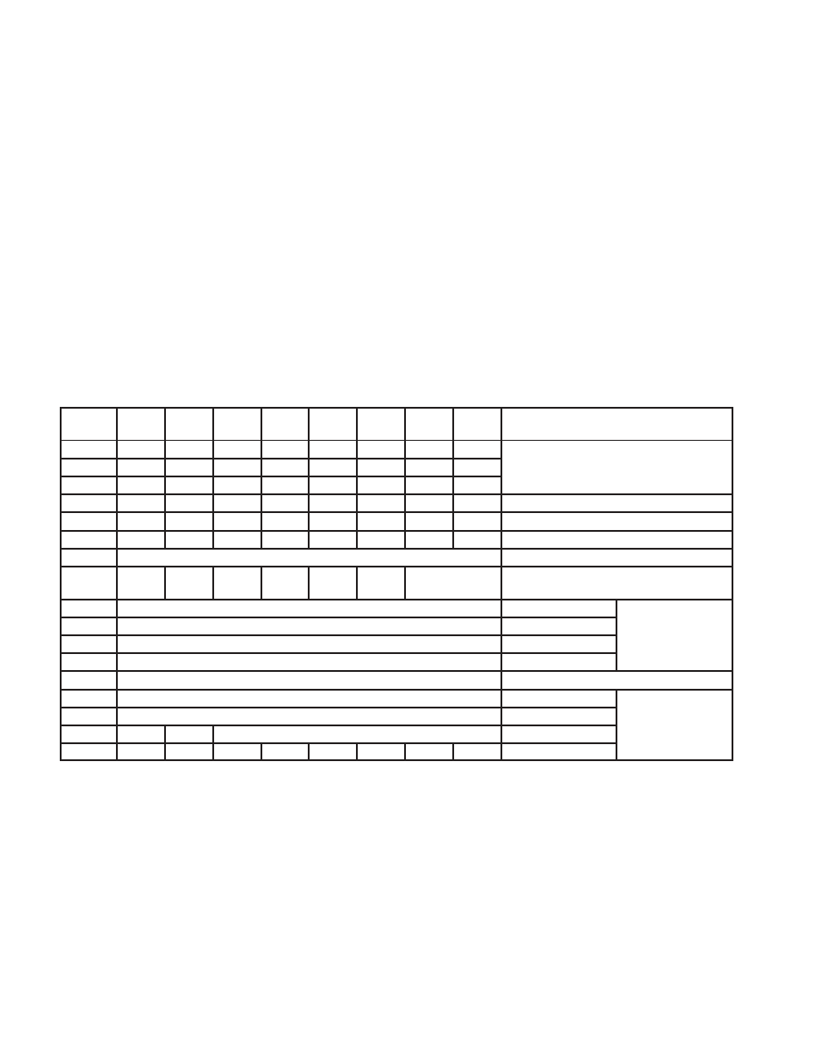
the horizontal blanking period following the line from which the data was retrieved. Table 22 shows the header format
and sequence of the ancillary data inserted into the video stream. This format is also used to store any VBI data into
the FIFO. The size of FIFO is 512 bytes. Therefore, the FIFO can store up to 11 lines of teletext data with the NTSC
NABTS standard.
Table 22. Ancillary Data Format and Sequence
BYTE
NO.
D7
(MSB)
D6
D5
D4
D3
D2
D1
D0
(LSB)
DESCRIPTION
0
Ancillary data preamble
1
Ancillary data preamble
2
1
3
NEP
EP
0
1
0
DID2
DID1
DID0
Data ID (DID)
4
NEP
EP
F5
F4
F3
F2
F1
F0
Secondary data ID (SDID)
5
NEP
EP
N5
N4
N3
N2
N1
N0
Number of 32 bit data (NN)
6
Video line # [7:0]
Internal data ID0 (IDID0)
7
0
Data
error
Match
#1
Match
#2
Video line # [9:8]
Internal data ID1 (IDID1)
8
1. Data
Data byte
1st word
9
2. Data
Data byte
1
word
10
3. Data
Data byte
11
4. Data
Data byte
:
m1. Data
Data byte
Nth word
m. Data
Data byte
N
word
NEP
EP
CS[5:0]
Check sum
4(N+2)1
1
0
Fill byte
EP:
Even parity for D0D5
NEP: Negated even parity
DID:
91h: Sliced data of VBI lines of first field
53h: Sliced data of line 24 to end of first field
55h: Sliced data of VBI lines of second field
97h: Sliced data of line 24 to end of second field
SDID:
This field holds the data format taken from the line mode register of the corresponding line.
NN:
Number of Dwords beginning with byte 8 through 4(N+2). This value is the number of Dwords where
each Dword is 4 bytes.
IDID0:
Transaction video line number [7:0]
相关PDF资料 |
PDF描述 |
|---|---|
| TVP5150AZQC | COLOR SIGNAL DECODER, PBGA48 |
| TVP5150APBSRG4 | COLOR SIGNAL DECODER, PQFP32 |
| TVP5150PBSRG4 | COLOR SIGNAL DECODER, PQFP32 |
| TVP5150PBSG4 | COLOR SIGNAL DECODER, PQFP32 |
| TVP5150PBS | COLOR SIGNAL DECODER, PQFP32 |
相关代理商/技术参数 |
参数描述 |
|---|---|
| TVP5150PBS | 功能描述:编码器、解码器、复用器和解复用器 VERY LOW POWER VIDEO DECODER RoHS:否 制造商:Micrel 产品:Multiplexers 逻辑系列:CMOS 位数: 线路数量(输入/输出):2 / 12 传播延迟时间:350 ps, 400 ps 电源电压-最大:2.625 V, 3.6 V 电源电压-最小:2.375 V, 3 V 最大工作温度:+ 85 C 安装风格:SMD/SMT 封装 / 箱体:QFN-44 封装:Tray |
| TVP5150PBS | 制造商:Texas Instruments 功能描述:IC DECODER VIDEO SMD |
| TVP5150PBSG4 | 功能描述:视频 IC VERY LOW POWER VIDEO DECODER RoHS:否 制造商:Fairchild Semiconductor 工作电源电压:5 V 电源电流:80 mA 最大工作温度:+ 85 C 封装 / 箱体:TSSOP-28 封装:Reel |
| TVP5150PBSR | 功能描述:视频 IC Very Low Power Video Decoder RoHS:否 制造商:Fairchild Semiconductor 工作电源电压:5 V 电源电流:80 mA 最大工作温度:+ 85 C 封装 / 箱体:TSSOP-28 封装:Reel |
| TVP5150PBSRG4 | 制造商:Texas Instruments 功能描述: |
发布紧急采购,3分钟左右您将得到回复。