- 您现在的位置:买卖IC网 > PDF目录98306 > TVP5150PBSG4 (TEXAS INSTRUMENTS INC) COLOR SIGNAL DECODER, PQFP32 PDF资料下载
参数资料
| 型号: | TVP5150PBSG4 |
| 厂商: | TEXAS INSTRUMENTS INC |
| 元件分类: | 颜色信号转换 |
| 英文描述: | COLOR SIGNAL DECODER, PQFP32 |
| 封装: | GREEN, PLASTIC, TQFP-32 |
| 文件页数: | 8/27页 |
| 文件大小: | 453K |
| 代理商: | TVP5150PBSG4 |
第1页第2页第3页第4页第5页第6页第7页当前第8页第9页第10页第11页第12页第13页第14页第15页第16页第17页第18页第19页第20页第21页第22页第23页第24页第25页第26页第27页
Detailed Description
12
SLES043 — September 2002
TVP5150
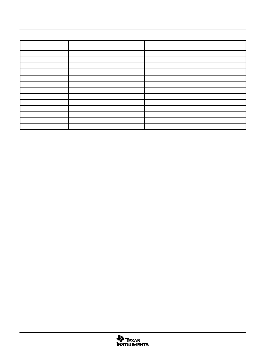
Table 2–1. Data Types Supported by the VDP (Continued)
LINE MODE REGISTER
(D0h–FBh) Bit[3:0]
SAMPLING RATE
(0Dh) Bit 7
NAME
DESCRIPTION
1000b
0
WSS, PAL S
Wide screen signal, PAL square
1000b
1
WSS, PAL 6
Wide screen signal, PAL ITU-R BT 601
1001b
0
WSS, NTSC S
Wide screen signal, NTSC, square
1001b
1
WSS, NTSC 6
Wide screen signal, NTSC, ITU-R BT 601
1010b
0
VITC, PAL S
Vertical interval timecode, PAL square
1010b
1
VITC, PAL 6
Vertical interval timecode PAL ITU-R BT 601
1011b
0
VITC, NTSC S
Vertical interval timecode, NTSC, square
1011b
1
VITC, NTSC 6
Vertical interval timecode, NTSC, ITU-R BT 601
1100b
0
VPS, PAL S
Video program system, PAL, square
1100b
1
VPS, PAL 6
Video program system, PAL, ITU-R BT 601
1101b
Custom
1110b
Custom
1111b
x
Active video
Active video/full field
At power up, the host interface is required to program the VDP-configuration RAM (VDP-CRAM) contents with
the lookup table. This is done through port address C3h. Each read or write from to this address auto
increments an internal counter to the next RAM location. To access the VDP-CRAM, the line mode registers
(D0h–FCh) must be programmed with FFh to avoid a conflict with the microprocessor and the VDP in both
writing and reading. Full field mode must also be disabled.
Available VBI lines are from line 6 to line 27 of both field 1 and field 2. Theoretically, each line can be any VBI
mode because the VDP processes VBI data in a line by line. When changing modes, the VDP must allow the
current transaction to complete through the delays of the VDP before switching the line mode register’s
contents. It must also complete the loading of the line mode registers before the next line starts processing.
The switch pixel number is set through registers CBh and CCh. Output data is available either through the
VBI-FIFO (B0h) or through dedicated registers at 90h–AFh, both of which are available from the host port.
2.6
VBI FIFO and Ancillary Data in Video Stream
Sliced VBI data can be output as ancillary data in the video stream in ITU-R BT.656 mode. VBI data is output
during the horizontal blanking period following the line from which the data was retrieved. The following table
shows the header format and sequence of the ancillary data inserted into the video stream. This format is also
used to store any VBI data into the FIFO. The size of FIFO is 512 bytes. Therefore, the FIFO can store up to
11 lines of Teletext data with NTSC NABST standard.
相关PDF资料 |
PDF描述 |
|---|---|
| TVP5150PBS | COLOR SIGNAL DECODER, PQFP32 |
| TVP5150PBSR | COLOR SIGNAL DECODER, PQFP32 |
| TVP5151IPBSQ1 | COLOR SIGNAL DECODER, PQFP32 |
| TVP5151IPBSRQ1 | COLOR SIGNAL DECODER, PQFP32 |
| TVP5151IPBSR | COLOR SIGNAL DECODER, PQFP32 |
相关代理商/技术参数 |
参数描述 |
|---|---|
| TVP5150PBSR | 功能描述:视频 IC Very Low Power Video Decoder RoHS:否 制造商:Fairchild Semiconductor 工作电源电压:5 V 电源电流:80 mA 最大工作温度:+ 85 C 封装 / 箱体:TSSOP-28 封装:Reel |
| TVP5150PBSRG4 | 制造商:Texas Instruments 功能描述: |
| TVP5151 | 制造商:TI 制造商全称:Texas Instruments 功能描述:Ultralow-Power NTSC/PAL/SECAM Video Decoder |
| TVP5151EVM | 功能描述:视频 IC 开发工具 TVP5151 Eval Mod RoHS:否 制造商:Texas Instruments 产品:Evaluation Boards 类型:YPbPr to RGBHV Converters 工具用于评估:LMH1251 工作电源电压:5 V |
| TVP5151IPBS | 功能描述:视频 IC UltraLo-Pwr NTSC/ RoHS:否 制造商:Fairchild Semiconductor 工作电源电压:5 V 电源电流:80 mA 最大工作温度:+ 85 C 封装 / 箱体:TSSOP-28 封装:Reel |
发布紧急采购,3分钟左右您将得到回复。