- 您现在的位置:买卖IC网 > PDF目录199556 > UDA1345TS/N2,118 (NXP SEMICONDUCTORS) Economy audio CODEC; Package: SOT341-1 (SSOP28); Container: Reel Pack, SMD, 13" PDF资料下载
参数资料
| 型号: | UDA1345TS/N2,118 |
| 厂商: | NXP SEMICONDUCTORS |
| 元件分类: | 消费家电 |
| 英文描述: | Economy audio CODEC; Package: SOT341-1 (SSOP28); Container: Reel Pack, SMD, 13" |
| 中文描述: | SPECIALTY CONSUMER CIRCUIT, PDSO28 |
| 封装: | 5.30 MM, PLASTIC, SSOP-28 |
| 文件页数: | 28/28页 |
| 文件大小: | 136K |
| 代理商: | UDA1345TS/N2,118 |
第1页第2页第3页第4页第5页第6页第7页第8页第9页第10页第11页第12页第13页第14页第15页第16页第17页第18页第19页第20页第21页第22页第23页第24页第25页第26页第27页当前第28页
2002 May 28
9
Philips Semiconductors
Product specication
Economy audio CODEC
UDA1345TS
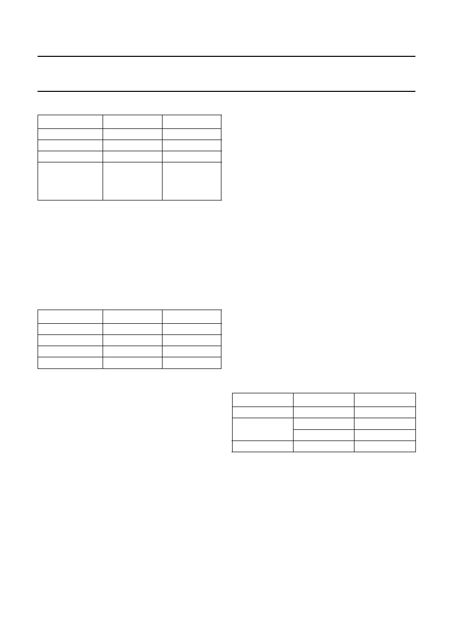
Table 2
Digital decimation lter characteristics
Note: the digital output level is inversely proportional to the
ADC analog power supply. This means that with a
constant analog input level and increasing power supply
the digital output level will decrease proportionally.
7.4
Interpolation lter (DAC)
The digital filter interpolates from 1 to 128fs by means of a
cascade of a recursive filter and an FIR filter.
Table 3
Digital interpolation lter characteristics
7.5
Double speed
Since the device supports a sampling range of
8 to 100 kHz, the device can support double speed (e.g.
for 44.1 kHz and 48 kHz sampling frequency) by just
doubling the system speed. In double speed all features
are available.
7.6
Noise shaper (DAC)
The 3rd-order noise shaper operates at 128fs. It shifts
in-band quantization noise to frequencies well above the
audio band. This noise shaping technique enables high
signal-to-noise ratios to be achieved. The noise shaper
output is converted into an analog signal using a filter
stream digital-to-analog converter.
7.7
The Filter Stream DAC (FSDAC)
The FSDAC is a semi-digital reconstruction filter that
converts the 1-bit data stream of the noise shaper to an
analog output voltage. The filter coefficients are
implemented as current sources and are summed at
virtual ground of the output operational amplifier. In this
way very high signal-to-noise performance and low clock
jitter sensitivity is achieved. A post filter is not needed due
to the inherent filter function of the DAC. On-board
amplifiers convert the FSDAC output current to an output
voltage signal capable of driving a line output.
The output voltage of the FSDAC is scaled proportionally
with the power supply voltage.
7.8
Power control
In the event that the DAC is powered-up or powered-down,
a cosine roll-off mute will be performed (when powering
down) or a cosine roll-up de-mute (when powering up) will
be performed. This is in order to prevent clicks when
powering up or down. This power-on/off mute takes
32
× 4 = 128 samples.
7.9
L3MODE or static pin control
The UDA1345TS can be used under L3 microcontroller
interface mode or under static pin control. The mode can
be set via the Mode Control (MC) pins MC1 (pin 8) and
MC2 (pin 21). The function of these pins is given in
Table 4.
Table 4
Mode Control pins MC1 and MC2
Important: in L3MODE the UDA1345TS is completely pin
and function compatible with the UDA1340M and the
UDA1344TS.
Note: the UDA1345TS does NOT support bass-boost and
treble.
ITEM
CONDITIONS
VALUE (dB)
Pass-band ripple
0
0.45fs
±0.05
Stop band
>0.55fs
60
Dynamic range
0
0.45fs
114
Overall gain when
a 0 dB signal is
input to ADC to
digital output
DC
1.16
ITEM
CONDITIONS
VALUE (dB)
Passband ripple
0
0.45fs
±0.03
Stopband
>0.55fs
65
Dynamic range
0
0.45fs
116.5
Gain
DC
3.5
MODE
MC2
MC1
L3MODE
LOW
Test modes
LOW
HIGH
LOW
Static pin mode
HIGH
相关PDF资料 |
PDF描述 |
|---|---|
| UDA1345TS/N2,112 | Economy audio CODEC; Package: SOT341-1 (SSOP28); Container: Tube |
| UDA1361TS/N1,112 | 96 kHz sampling 24-bit stereo audio ADC; Package: SOT369-1 (SSOP16); Container: Tube |
| UDA1361TS/N1,118 | 96 kHz sampling 24-bit stereo audio ADC; Package: SOT369-1 (SSOP16); Container: Reel Pack, SMD, 13" |
| UDA1380HN/N2,118 | Stereo audio coder-decoder for MD, CD and MP3; Package: SOT617-1 (HVQFN32); Container: Reel Pack, SMD, 13" |
| UDA1380TT | Stereo audio coder-decoder for MD, CD and MP3 |
相关代理商/技术参数 |
参数描述 |
|---|---|
| UDA1350AH | 制造商:PHILIPS 制造商全称:NXP Semiconductors 功能描述:IEC 958 audio DAC |
| UDA1350ATS | 制造商:PHILIPS 制造商全称:NXP Semiconductors 功能描述:IEC 958 audio DAC |
| UDA1351 | 制造商:PHILIPS 制造商全称:NXP Semiconductors 功能描述:96 kHz IEC 958 audio DAC |
| UDA1351H | 制造商:PHILIPS 制造商全称:NXP Semiconductors 功能描述:96 kHz IEC 958 audio DAC |
| UDA1351H/N1,551 | 功能描述:数模转换器- DAC 96 KHZ SPDIF DAC RoHS:否 制造商:Texas Instruments 转换器数量:1 DAC 输出端数量:1 转换速率:2 MSPs 分辨率:16 bit 接口类型:QSPI, SPI, Serial (3-Wire, Microwire) 稳定时间:1 us 最大工作温度:+ 85 C 安装风格:SMD/SMT 封装 / 箱体:SOIC-14 封装:Tube |
发布紧急采购,3分钟左右您将得到回复。