- 您现在的位置:买卖IC网 > Datasheet目录368 > W25X64VZEIG (Winbond Electronics)IC FLASH 64MBIT 75MHZ 8WSON Datasheet资料下载
参数资料
| 型号: | W25X64VZEIG |
| 厂商: | Winbond Electronics |
| 文件页数: | 24/50页 |
| 文件大小: | 0K |
| 描述: | IC FLASH 64MBIT 75MHZ 8WSON |
| 标准包装: | 63 |
| 系列: | SpiFlash® |
| 格式 - 存储器: | 闪存 |
| 存储器类型: | FLASH |
| 存储容量: | 64M(8M x 8) |
| 速度: | 75MHz |
| 接口: | SPI 串行 |
| 电源电压: | 2.7 V ~ 3.6 V |
| 工作温度: | -40°C ~ 85°C |
| 封装/外壳: | 8-WDFN 裸露焊盘 |
| 供应商设备封装: | 8-WSON(8x6) |
| 包装: | 管件 |
第1页第2页第3页第4页第5页第6页第7页第8页第9页第10页第11页第12页第13页第14页第15页第16页第17页第18页第19页第20页第21页第22页第23页当前第24页第25页第26页第27页第28页第29页第30页第31页第32页第33页第34页第35页第36页第37页第38页第39页第40页第41页第42页第43页第44页第45页第46页第47页第48页第49页第50页
�� �
�
�W25X16,� W25X16A,� W25X32,� W25X64�
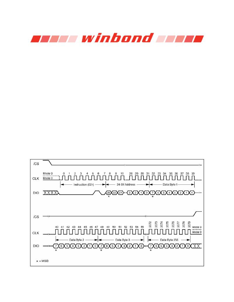
�12.2.10� Page� Program� (02h)�
�The� Page� Program� instruction� allows� up� to� 256� bytes� of� data� to� be� programmed� at� previously� erased�
�to� all� 1s� (FFh)� memory� locations.� A� Write� Enable� instruction� must� be� executed� before� the� device� will�
�accept� the� Page� Program� Instruction� (Status� Register� bit� WEL� must� equal� 1).� The� instruction� is�
�initiated� by� driving� the� /CS� pin� low� then� shifting� the� instruction� code� “02h”� followed� by� a� 24-bit� address�
�(A23-A0)� and� at� least� one� data� byte,� into� the� DIO� pin.� The� /CS� pin� must� be� held� low� for� the� entire�
�length� of� the� instruction� while� data� is� being� sent� to� the� device.� The� Page� Program� instruction�
�sequence� is� shown� in� figure� 11.�
�If� an� entire� 256� byte� page� is� to� be� programmed,� the� last� address� byte� (the� 8� least� significant� address�
�bits)� should� be� set� to� 0.� If� the� last� address� byte� is� not� zero,� and� the� number� of� clocks� exceed� the�
�remaining� page� length,� the� addressing� will� wrap� to� the� beginning� of� the� page.� In� some� cases,� less�
�than� 256� bytes� (a� partial� page)� can� be� programmed� without� having� any� effect� on� other� bytes� within� the�
�same� page.� One� condition� to� perform� a� partial� page� program� is� that� the� number� of� clocks� can� not�
�exceed� the� remaining� page� length.� If� more� than� 256� bytes� are� sent� to� the� device� the� addressing� will�
�wrap� to� the� beginning� of� the� page� and� overwrite� previously� sent� data.�
�As� with� the� write� and� erase� instructions,� the� /CS� pin� must� be� driven� high� after� the� eighth� bit� of� the� last�
�byte� has� been� latched.� If� this� is� not� done� the� Page� Program� instruction� will� not� be� executed.� After� /CS�
�is� driven� high,� the� self-timed� Page� Program� instruction� will� commence� for� a� time� duration� of� tpp� (See�
�AC� Characteristics).� While� the� Page� Program� cycle� is� in� progress,� the� Read� Status� Register�
�instruction� may� still� be� accessed� for� checking� the� status� of� the� BUSY� bit.� The� BUSY� bit� is� a� 1� during�
�the� Page� Program� cycle� and� becomes� a� 0� when� the� cycle� is� finished� and� the� device� is� ready� to� accept�
�other� instructions� again.� After� the� Page� Program� cycle� has� finished� the� Write� Enable� Latch� (WEL)� bit�
�in� the� Status� Register� is� cleared� to� 0.� The� Page� Program� instruction� will� not� be� executed� if� the�
�addressed� page� is� protected� by� the� Block� Protect� (BP2,� BP1,� and� BP0)� bits� (see� Status� Register�
�Memory� Protection� table).�
�Figure� 11.� Page� Program� Instruction� Sequence� Diagram�
�-� 24� -�
�相关PDF资料 |
PDF描述 |
|---|---|
| W25X80AVDAIZ | IC FLASH 16MBIT 100MHZ 8DIP |
| W29GL032CB7A | IC FLASH 32MBIT 70NS 48TFBGA |
| W29GL064CB7S | IC FLASH 64MBIT 70NS 48TSOP |
| W29GL128CL9T | IC FLASH 128MBIT 90NS 56TSOP |
| W631GG6KB-15 | IC DDR3 SDRAM 1GBIT 96WBGA |
相关代理商/技术参数 |
参数描述 |
|---|---|
| W25X64VZEIZ | 制造商:WINBOND 制造商全称:Winbond 功能描述:16M-BIT, 32M-BIT, AND 64M-BIT SERIAL FLASH MEMORY WITH 4KB SECTORS AND DUAL OUTPUT SPI |
| W25X64VZPI | 制造商:WINBOND 制造商全称:Winbond 功能描述:16M-BIT, 32M-BIT, AND 64M-BIT SERIAL FLASH MEMORY WITH 4KB SECTORS AND DUAL OUTPUT SPI |
| W25X64VZPIG | 制造商:WINBOND 制造商全称:Winbond 功能描述:16M-BIT, 32M-BIT, AND 64M-BIT SERIAL FLASH MEMORY WITH 4KB SECTORS AND DUAL OUTPUT SPI |
| W25X64VZPIZ | 制造商:WINBOND 制造商全称:Winbond 功能描述:16M-BIT, 32M-BIT, AND 64M-BIT SERIAL FLASH MEMORY WITH 4KB SECTORS AND DUAL OUTPUT SPI |
| W25X80 | 制造商:WINBOND 制造商全称:Winbond 功能描述:The W25X10 (1M-bit), W25X20 (2M-bit), W25X40 (4M-bit) and W25X80 (8M-bit) Serial Flash memories provide a storage solution for systems with limited space, pins and power. |
发布紧急采购,3分钟左右您将得到回复。