- 您现在的位置:买卖IC网 > PDF目录68583 > WJLXT901ALCA4 (CORTINA SYSTEMS INC) DATACOM, ETHERNET TRANSCEIVER, PQFP64 PDF资料下载
参数资料
| 型号: | WJLXT901ALCA4 |
| 厂商: | CORTINA SYSTEMS INC |
| 元件分类: | 网络接口 |
| 英文描述: | DATACOM, ETHERNET TRANSCEIVER, PQFP64 |
| 封装: | ROHS COMPLIANT, LQFP-64 |
| 文件页数: | 48/48页 |
| 文件大小: | 621K |
| 代理商: | WJLXT901ALCA4 |
第1页第2页第3页第4页第5页第6页第7页第8页第9页第10页第11页第12页第13页第14页第15页第16页第17页第18页第19页第20页第21页第22页第23页第24页第25页第26页第27页第28页第29页第30页第31页第32页第33页第34页第35页第36页第37页第38页第39页第40页第41页第42页第43页第44页第45页第46页第47页当前第48页
Intel
LXT901A/907A Universal 3.3 V Ethernet Transceiver
Datasheet
9
Document Number: 249098
Revision Number: 003
Revision Date: 27-Nov-2005
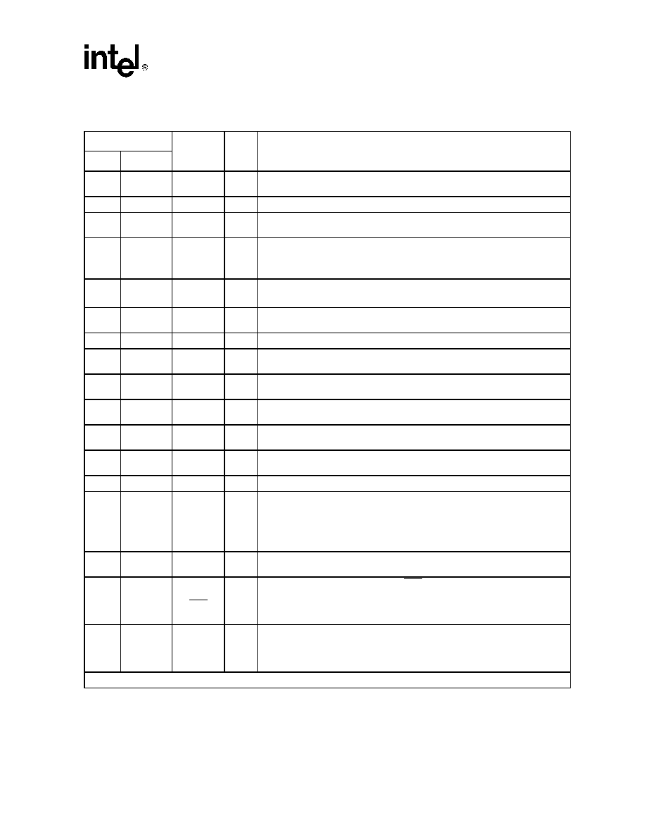
Table 1.
Signal Descriptions
Pin #
Symbol
I/O1
Description
PLCC
LQFP
1
34
10
56
VCC1
VCC2
–
Power Supply 1 and 2. Power supply inputs of +3.3 volts.
–
9
VCCA
–
Analog Supply. (+3.3V)
2
3
11
12
CIP
CIN
I
AUI Collision Pair. Differential input to the AUI transceiver CI circuit. The input is
collision signaling or SQE.
413
NTH
I
Normal Threshold. Selects normal or reduced threshold.
When NTH is High, the normal TP squelch threshold is in effect.
When NTH is Low, the normal TP squelch threshold is reduced by 4.5 dB.
5
6
14
15
MD0
MD1
I
Mode Select 0 (MD0) and Mode Select 1 (MD1). Mode select pins determine the
controller compatibility mode in accordance with Table 2.
819
LI
I
Link Test Enable. Controls Link Integrity Test; enabled when LI = High, disabled
when LI = Low
921
JAB
O
Jabber Indicator. Output goes High to indicate Jabber state.
10
22
TEST
I
Test. For Intel internal use only.
It is recommended to tie this pin High externally.
11
23
TCLK
O
Transmit Clock. A 10 MHz clock output. This clock signal should be directly
connected to the transmit clock input of the controller.
12
24
TXD
I
Transmit Data. Input signal containing NRZ data to be transmitted on the
network. Connect TXD directly to the transmit data output of the controller.
13
25
TEN
I
Transmit Enable. Enables data transmission and starts the watchdog timer.
Synchronous to TCLK (see Test Specifications for details).
14
15
26
27
CLKO
CLKI
O
I
Crystal Oscillator. A 20 MHz crystal must be connected across these pins, or a
20 MHz clock applied at CLKI with CLKO left open.
16
28
COL
O
Collision Detect. Output which drives the collision detect input of the controller.
17
29
AUTOSEL
I
Automatic Port Select.
When High, automatic port selection is enabled (the 901A/907A defaults to the
AUI port only if TP link integrity = Fail).
When Low, manual port selection is enabled (the PAUI pin determines the active
port).
18
34
LEDR
OD
Receive LED. Open drain driver for the receive indicator LED. Output is pulled
Low during receive.
19
35
LEDT/
PDN
OD
Transmit LED (LEDT)/Power-Down (PDN). Open drain driver for the transmit
indicator. Output is pulled Low during transmit. Do not allow this pin to float. If
unused, tie High.
If externally pulled Low, the LXT901A/907A goes to power-down state.
20
36
LEDL
OD
Link LED. Open drain driver for link integrity indicator. Output is pulled Low
during link test pass.
If externally tied Low, internal circuitry is forced to “Link Pass” state and the
LXT901A/907A Transceiver transmits link test pulses continuously.
1. I/O Column Coding: I = Input, O = Output, OD = Open Drain
相关PDF资料 |
PDF描述 |
|---|---|
| WJLXT907ALCA4 | DATACOM, ETHERNET TRANSCEIVER, PQFP64 |
| WJLXT905LC.C2 | DATACOM, ETHERNET TRANSCEIVER, PQFP32 |
| WJLXT905LE.C2 | DATACOM, ETHERNET TRANSCEIVER, PQFP32 |
| WJLXT905LC.C2 | DATACOM, ETHERNET TRANSCEIVER, PQFP32 |
| WJLXT905LE.C2 | DATACOM, ETHERNET TRANSCEIVER, PQFP32 |
相关代理商/技术参数 |
参数描述 |
|---|---|
| WJLXT901ALCA4-865823 | 制造商:Cortina Systems Inc 功能描述:WJLXT901ALC.A4-865823 |
| WJLXT905LC.C2 | 功能描述:IC 10BASE-T TXCVR 3V/5V 32-LQFP RoHS:是 类别:集成电路 (IC) >> 接口 - 驱动器,接收器,收发器 系列:- 标准包装:1,000 系列:- 类型:收发器 驱动器/接收器数:2/2 规程:RS232 电源电压:3 V ~ 5.5 V 安装类型:表面贴装 封装/外壳:16-SOIC(0.295",7.50mm 宽) 供应商设备封装:16-SOIC 包装:带卷 (TR) |
| WJLXT905LC.C2 S E001 | 制造商:Intel 功能描述:UNIVERSAL 10BASE-T TRANSCEIVER WITH 3.3 V SUPPORT |
| WJLXT905LC.C2-863532 | 制造商:Cortina Systems Inc 功能描述:PN may be NE SA CE AP NA SE 制造商:Cortina Systems 功能描述:PN may be NE SA CE AP NA SE |
| WJLXT905LC.C2-863540 | 制造商:Cortina Systems Inc 功能描述:UNIVERSAL 10BASE-T TRANSCEIVER WITH 3.3 V SUPPORT 制造商:Cortina Systems 功能描述:UNIVERSAL 10BASE-T TRANSCEIVER WITH 3.3 V SUPPORT |
发布紧急采购,3分钟左右您将得到回复。