- 您现在的位置:买卖IC网 > PDF目录16986 > XRD98L63ZEVAL (Exar Corporation)EVAL BOARD FOR XRD98L63 PDF资料下载
参数资料
| 型号: | XRD98L63ZEVAL |
| 厂商: | Exar Corporation |
| 文件页数: | 13/41页 |
| 文件大小: | 0K |
| 描述: | EVAL BOARD FOR XRD98L63 |
| 标准包装: | 1 |
| 系列: | * |
第1页第2页第3页第4页第5页第6页第7页第8页第9页第10页第11页第12页当前第13页第14页第15页第16页第17页第18页第19页第20页第21页第22页第23页第24页第25页第26页第27页第28页第29页第30页第31页第32页第33页第34页第35页第36页第37页第38页第39页第40页第41页
XRD98L63
20
Rev.1.01
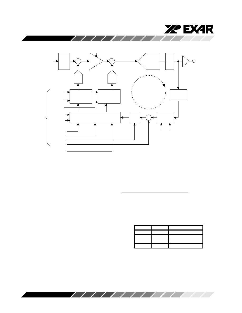
CDS
12-bit ADC
Hot Pixel
C lipper
Pixel
Averager
+
-
+
Even & Odd
Coarse
Accumulators
Even & Odd
Fine
Accumulators
Offset Calibration Logic
PGA
Reg
Hold
OB[7:0]
Gain[9:0]
DB[11:0]
CDAC
FDAC
+
B lack Level
O ffset Calibration
Loop
DNS[1:0]
ManCAL
CDE, CDO
From Serial
Interface
Registers
CCD
signal
W L[11:0]
Mode
DNS
Filter
FDE, FDO
OBL[11:0]
Gain[9:0]
Avg[1:0]
OBdel[2:0]
From Gain Logic
Figure 12. Detailed Block Diagram of the Black Level Offset Calibration Logic
Offset Difference
Next, the Offset register value, OB[7:0], is subtracted
from the OB pixel average. If the difference is positive,
the offset DACs are adjusted to reduce the effective
ADC output code. If the difference is negative, the
offset DACs are adjusted to increase the effective ADC
output code. The DNS option will affect how the DAC
adjustments are made.
Coarse & Fine Accumulators
The Coarse and Fine Accumulators are the registers
which hold the digital codes for the Coarse and Fine
Offset DACs. The Offset DAC adjustments are made
by adding to or subtracting from the value in the Fine
accumulator. If there is an overflow or underflow in the
Fine Accumulator, the Fine Accumulator is reset to it’s
mid-scale value, and the Coarse Accumulator is
incremented or decremented accordingly.
In the Multiple Gain Mode, there are separate accumu-
lators for even and odd lines.
DNS[1]
DNS[0]
DNS Filter Width
0
OFF
0
1
Narrow (default)
1
0
Medium
1
Wide
Calibration Options
Digital Noise Suppression (DNS) Filter
The purpose of this option is to eliminate small
changes in the Black Level offset by making the
calibration system less sensitive to small changes in
the measured offset. In this mode, the user has the
option of selecting from three filter settings, see Table 5.
Table 5. DNS Threshold Programming
To activate the Digital Noise Suppression mode, write
to the DNS[1:0] bits in the Calibration register.
By default, the Digital Noise Suppression is ON and set
to the narrow filter width.
相关PDF资料 |
PDF描述 |
|---|---|
| RCB13DHLN | CONN EDGECARD 26POS DIP .050 SLD |
| P1330R-104K | INDUCTOR POWER 100.0UH SMD |
| VI-270-EY | CONVERTER MOD DC/DC 5V 50W |
| 0210490388 | CABLE JUMPER 1.25MM .030M 32POS |
| VE-20X-EY | CONVERTER MOD DC/DC 5.2V 50W |
相关代理商/技术参数 |
参数描述 |
|---|---|
| XRDAN27 | 制造商:EXAR 制造商全称:EXAR 功能描述:Compensating for Zero Order Hold Effects |
| XRDAN28 | 制造商:EXAR 制造商全称:EXAR 功能描述:Frequency Response Effects of Overampling and Averaging on A/D Output Data |
| XRDAN29 | 制造商:EXAR 制造商全称:EXAR 功能描述:Criteria for Accurate Sampling of Analog Signals |
| XRDAN30 | 制造商:EXAR 制造商全称:EXAR 功能描述:CMOS Current Output D/A Converter Design Concepts for Wide Bandwidth Applications |
| XR-E | 制造商:CREE 制造商全称:Cree, Inc 功能描述:XLamp XR-E and XR-C LED Binning and Labeling |
发布紧急采购,3分钟左右您将得到回复。