参数资料
| 型号: | XRT71D04IVTR |
| 厂商: | Exar Corporation |
| 文件页数: | 18/22页 |
| 文件大小: | 0K |
| 描述: | IC JITTER ATTENUATOR 4CH 80TQFP |
| 标准包装: | 1,000 |
| 类型: | * |
| PLL: | 是 |
| 输入: | 时钟 |
| 输出: | 时钟 |
| 电路数: | 1 |
| 比率 - 输入:输出: | 4:3 |
| 差分 - 输入:输出: | 无/无 |
| 频率 - 最大: | 44.736MHz |
| 除法器/乘法器: | 无/无 |
| 电源电压: | 3.135 V ~ 5.25 V |
| 工作温度: | -40°C ~ 85°C |
| 安装类型: | 表面贴装 |
| 封装/外壳: | 80-LQFP |
| 供应商设备封装: | 80-TQFP(14x14) |
| 包装: | 带卷 (TR) |
á
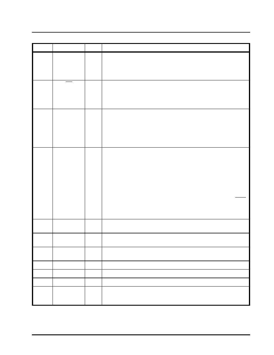
XRT71D04
4 CHANNEL E3/DS3/STS-1 JITTER ATTENUATOR, STS-1 TO DS3 DESYNCHRONIZER
REV. 1.1.1
4
12
MODE_CTRL
I
Mode Control:
When “High” in Multimode, all channels are independent. When “Low”, the Mas-
ter Channel (channel_0) controls DS3/E3_n, STS1_n, RCLKES, FSS and
MCLK_n. DJA is NOT affected.
Internal 50 K Ohm pull-up resistor.
13
ICT
I
In Circuit Testing Input. (Active low):
With this pin tied to ground, all output pins will be in high impedance mode for in-
circuit-testing.
For normal operation this input pin should be tied to VDD.
Internal 50 K Ohm pull-up resistor.
14
HOST
I
Host/Hardware Mode Select:
An active-high input enables the Host mode. Data is written to the command reg-
isters to configure the XRT71D04.
In the Host mode, the states of discrete input pins are inactive.
An active-low input enables the Hardware Mode.In this mode, the discrete inputs
are active.
Internal 50 K Ohm pull-down resistor.
15
FLRST
I
FIFO Limit Reset
Hardware Mode
Whenever the FIFO is within 2 bits of either underflow or overflow, the FL_n will
be set high.
This pin allows the user to reset the state of FL_n, (FIFO Limit) output pin.
This pin when pulsed “High”, resets the the FL_n output pin, (toggles to GND).
NOTE: The FL_n could be set “High” again if the FIFO is within 2 bits of either
underflow or overflow.
Host Mode
Reading the FL_n bits in the status registers clears this FL_n pin. Master Reset
also clears the FL_n output.
This pin is tied to GND. FLRST has no effect in this mode.
Internal 50 K Ohm pull-down resistor.
16
RRNEG_3
O
Received Recovered Negative Data (De-Jittered) Output - channel 3:
See description of pin 6
17
RRPOS_3
O
Received Positive Data (De-Jittered) Output - channel 3:
See description of pin 5
18
RRCLK_3
O
Received Recovered Output (De-jittered) Clock - channel 3:
See description of pin 4
19
GND
O
Digital Ground
20
AVDD
****
Analog Power Supply = 5V±5% or 3.3V±5%
21
AGND
****
Analog Ground
22
FL_0
O
FIFO Limit - channel 0:
This output pin is driven high whenever the internal FIFO comes within two-bits of
being either underflow or overflow.
PIN DESCRIPTION
PIN #NAME
TYPE
DESCRIPTION
相关PDF资料 |
PDF描述 |
|---|---|
| VI-2T1-MW-S | CONVERTER MOD DC/DC 12V 100W |
| MS27474T24F29S | CONN RCPT 29POS JAM NUT W/SCKT |
| V28A6V5H200BF2 | CONVERTER MOD DC/DC 6.5V 200W |
| V28A6V5H200B2 | CONVERTER MOD DC/DC 6.5V 200W |
| XRT71D03IVTR-F | IC JITTER ATTENUATOR 3CH 64TQFP |
相关代理商/技术参数 |
参数描述 |
|---|---|
| XRT7250 | 制造商:EXAR 制造商全称:EXAR 功能描述:DS3/E3 FRAMER IC |
| XRT7250ES-PCI | 功能描述:界面开发工具 Evaluation Board for XRT7250 Series RoHS:否 制造商:Bourns 产品:Evaluation Boards 类型:RS-485 工具用于评估:ADM3485E 接口类型:RS-485 工作电源电压:3.3 V |
| XRT7250IQ100 | 制造商:EXAR 制造商全称:EXAR 功能描述:DS3/E3 FRAMER IC |
| XRT7288 | 制造商:EXAR 制造商全称:EXAR 功能描述:CEPT1 Line Interface |
| XR-T7288 | 制造商:EXAR 制造商全称:EXAR 功能描述:CEPT1 Line Interface |
发布紧急采购,3分钟左右您将得到回复。