- 您现在的位置:买卖IC网 > PDF目录17319 > ZL9101EVAL1Z (Intersil)EVALUATION BOARD 1 ZL9101 PDF资料下载
参数资料
| 型号: | ZL9101EVAL1Z |
| 厂商: | Intersil |
| 文件页数: | 11/19页 |
| 文件大小: | 0K |
| 描述: | EVALUATION BOARD 1 ZL9101 |
| 标准包装: | 1 |
| 主要目的: | DC/DC,步降 |
| 输出及类型: | 1,非隔离 |
| 输出电压: | 0.6 ~ 4 V |
| 电流 - 输出: | 12A |
| 输入电压: | 12V |
| 稳压器拓扑结构: | 降压 |
| 频率 - 开关: | 615kHz |
| 板类型: | 完全填充 |
| 已供物品: | 板 |
| 已用 IC / 零件: | ZL9101 |
�� �
�
�ZL9101M�
�3.� Continue� operating� for� a� given� delay� period,� followed� by�
�shutdown� if� the� fault� still� exists.�
�4.� Continue� operating� through� the� fault� (this� could� result� in�
�permanent� damage� to� the� power� supply).�
�5.� Initiate� an� immediate� shutdown.�
�The� default� response� from� an� overcurrent� fault� is� an� immediate�
�shutdown� of� the� controller.� The� controller� continuously� checks� for�
�the� presence� of� the� fault� condition,� and� if� the� fault� condition� no�
�longer� exists,� the� device� is� re-enabled.�
�Please� refer� to� Application� Note� AN2033� for� details� on� how� to�
�select� specific� overcurrent� fault� response� options� via� I� 2� C/SMBus.�
�Thermal� Overload� Protection�
�The� ZL9101M� includes� a� thermal� sensor� that� continuously�
�measures� the� internal� temperature� of� the� module� and� shuts�
�down� the� controller� when� the� temperature� exceeds� the� preset�
�limit.� The� default� temperature� limit� is� set� to� +125°C� in� the�
�factory,� but� the� user� may� set� the� limit� to� a� different� value� if�
�desired.� See� Application� Note� AN2033� for� details.� Note� that�
�setting� a� higher� thermal� limit� via� the� I� 2� C/SMBus� interface� may�
�result� in� permanent� damage� to� the� controller.� Once� the� module�
�has� been� disabled� due� to� an� internal� temperature� fault,� the� user�
�may� select� one� of� several� fault� response� options� as� follows:�
�1.� Initiate� a� shutdown� and� attempt� to� restart� an� infinite� number�
�of� times� with� a� preset� delay� period� between� attempts.�
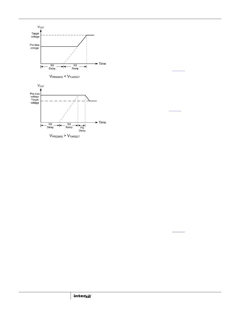
�FIGURE� 13.� OUTPUT� RESPONSES� TO� PRE-BIAS� VOLTAGES�
�If� a� pre-bias� voltage� higher� than� the� target� voltage� exists� after� the�
�pre-configured� delay� period� has� expired,� the� target� voltage� is� set�
�to� match� the� existing� pre-bias� voltage,� and� both� drivers� are�
�enabled� with� a� PWM� duty� cycle� that� would� ideally� create� the�
�pre-bias� voltage.�
�Once� the� pre-configured� soft-start� ramp� period� has� expired,� the�
�PG� pin� is� asserted� (assuming� the� pre-bias� voltage� is� not� higher�
�than� the� overvoltage� limit).� The� PWM� then� adjusts� its� duty� cycle�
�to� match� the� original� target� voltage,� and� the� output� ramps� down�
�to� the� preconfigured� output� voltage.�
�If� a� pre-bias� voltage� higher� than� the� overvoltage� limit� exists,� the�
�device� does� not� initiate� a� turn-on� sequence� and� declares� an�
�overvoltage� fault� condition� to� exist.� In� this� case,� the� device�
�responds� based� on� the� output� overvoltage� fault� response� method�
�that� has� been� selected.� See� “Output� Overvoltage� Protection”� on�
�page� 10� for� response� options� due� to� an� overvoltage� condition.�
�Note� that� pre-bias� protection� is� not� offered� for� current� sharing�
�groups� that� also� have� tracking� enabled.� V� DD� must� be� tied� to� V� IN�
�for� proper� prebias� start-up� in� single� module� operation.�
�Output� Overcurrent� Protection�
�The� ZL9101M� can� protect� the� power� supply� from� damage� if� the�
�output� is� shorted� to� ground� or� if� an� overload� condition� is� imposed�
�on� the� output.� The� following� overcurrent� protection� response�
�options� are� available:�
�1.� Initiate� a� shutdown� and� attempt� to� restart� an� infinite� number�
�of� times� with� a� preset� delay� period� between� attempts.�
�2.� Initiate� a� shutdown� and� attempt� to� restart� a� preset� number� of�
�times� with� a� preset� delay� period� between� attempts.�
�11�
�2.� Initiate� a� shutdown� and� attempt� to� restart� a� preset� number� of�
�times� with� a� preset� delay� period� between� attempts.�
�3.� Continue� operating� for� a� given� delay� period,� followed� by�
�shutdown� if� the� fault� still� exists.�
�4.� Continue� operating� through� the� fault� (this� could� result� in�
�permanent� damage� to� the� power� supply).�
�5.� Initiate� an� immediate� shutdown.�
�If� the� user� has� configured� the� module� to� restart,� the� controller�
�waits� the� preset� delay� period� (if� configured� to� do� so)� and� then�
�checks� the� module� temperature.� If� the� temperature� has� dropped�
�below� a� threshold� that� is� approximately� +15°C� lower� than� the�
�selected� temperature� fault� limit,� the� controller� attempts� to�
�re-start.� If� the� temperature� still� exceeds� the� fault� limit,� the�
�controller� waits� the� preset� delay� period� and� retries� again.�
�The� default� response� from� a� temperature� fault� is� an� immediate�
�shutdown� of� the� module.� The� controller� continuously� checks� for�
�the� fault� condition,� and� once� the� fault� has� cleared,� the� ZL9101M�
�is� re-enabled.�
�Please� refer� to� Application� Note� AN2033� for� details� on� how� to�
�select� specific� temperature� fault� response� options� via�
�I� 2� C/SMBus.�
�I� 2� C/SMBus� Module� Address� Selection�
�Each� module� must� have� its� own� unique� serial� address� to�
�distinguish� between� other� devices� on� the� bus.� The� module�
�address� is� set� by� connecting� a� resistor� between� the� SA� pin� and�
�SGND.� Table� 2� lists� the� available� module� addresses.�
�FN7669.4�
�January� 20,� 2012�
�相关PDF资料 |
PDF描述 |
|---|---|
| GEC19DREN-S13 | CONN EDGECARD 38POS .100 EXTEND |
| GEC19DREH-S13 | CONN EDGECARD 38POS .100 EXTEND |
| EEC19DRTS-S13 | CONN EDGECARD 38POS .100 EXTEND |
| EBC10DRTI-S13 | CONN EDGECARD 20POS .100 EXTEND |
| EEC19DRES-S13 | CONN EDGECARD 38POS .100 EXTEND |
相关代理商/技术参数 |
参数描述 |
|---|---|
| ZL9101M | 制造商:INTERSIL 制造商全称:Intersil Corporation 功能描述:Digital DC/DC PMBus 12A Module |
| ZL9101M_11 | 制造商:INTERSIL 制造商全称:Intersil Corporation 功能描述:Digital DC/DC PMBus 12A Module |
| ZL9101M_1104 | 制造商:INTERSIL 制造商全称:Intersil Corporation 功能描述:Digital DC/DC PMBus 12A Module |
| ZL9101MIRZ | 功能描述:MODULE DGTL DC-DC 12A 21QFN RoHS:是 类别:电源 - 板载 >> DC DC Converters 系列:ZL9101M 标准包装:15 系列:Econoline REC3-DR 类型:隔离 输出数:2 电压 - 输入(最小):4.5V 电压 - 输入(最大):5.5V Voltage - Output 1:5V Voltage - Output 2:-5V Voltage - Output 3:- 电流 - 输出(最大):300mA,300mA 电源(瓦) - 制造商系列:3W 电压 - 隔离:1kV(1000V) 特点:- 安装类型:表面贴装 封装/外壳:24-DIP SMD 模块(18 引线) 尺寸/尺寸:1.26" L x 0.80" W x 0.44" H(32.0mm x 20.3mm x 11.2mm) 包装:管件 工作温度:-40°C ~ 80°C 效率:75% 电源(瓦特)- 最大:3W 其它名称:10005457 |
| ZL9101MIRZ-T | 功能描述:DCDC DGTL PMBUS MODULE 12A 21QFN RoHS:是 类别:电源 - 板载 >> DC DC Converters 系列:ZL9101M 标准包装:10 系列:PT4570 类型:隔离 输出数:1 电压 - 输入(最小):36V 电压 - 输入(最大):75V Voltage - Output 1:9V Voltage - Output 2:- Voltage - Output 3:- 电流 - 输出(最大):3.3A 电源(瓦) - 制造商系列:30W 电压 - 隔离:1.5kV(1500V) 特点:- 安装类型:表面贴装 封装/外壳:19-SIP SMD 模块 尺寸/尺寸:3.00" L x 1.19" W x 0.50" H(76.2mm x 30.2mm x 12.7mm) 包装:托盘 工作温度:-40°C ~ 85°C 效率:84% 电源(瓦特)- 最大:30W |
发布紧急采购,3分钟左右您将得到回复。