- 您现在的位置:买卖IC网 > PDF目录17319 > ZL9101EVAL1Z (Intersil)EVALUATION BOARD 1 ZL9101 PDF资料下载
参数资料
| 型号: | ZL9101EVAL1Z |
| 厂商: | Intersil |
| 文件页数: | 9/19页 |
| 文件大小: | 0K |
| 描述: | EVALUATION BOARD 1 ZL9101 |
| 标准包装: | 1 |
| 主要目的: | DC/DC,步降 |
| 输出及类型: | 1,非隔离 |
| 输出电压: | 0.6 ~ 4 V |
| 电流 - 输出: | 12A |
| 输入电压: | 12V |
| 稳压器拓扑结构: | 降压 |
| 频率 - 开关: | 615kHz |
| 板类型: | 完全填充 |
| 已供物品: | 板 |
| 已用 IC / 零件: | ZL9101 |
�� �
�
�ZL9101M�
�Functional� Description�
�I� 2� C/SMBus� Communications�
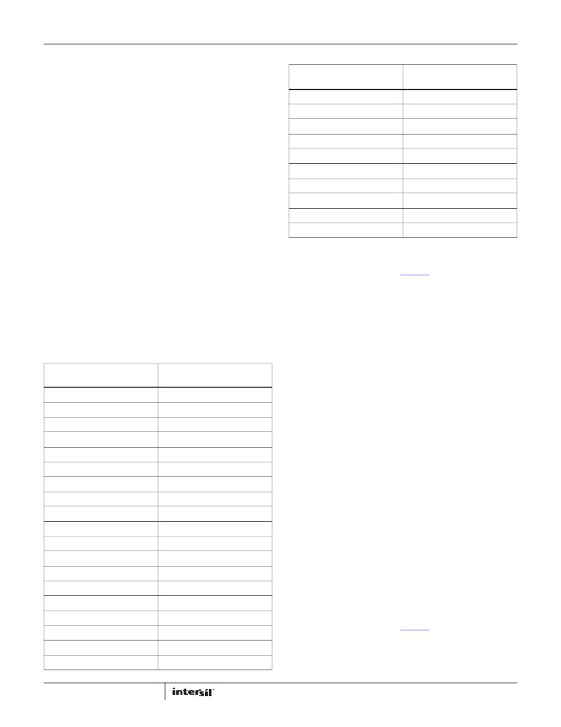
�TABLE� 1.� OUTPUT� VOLTAGE� RESISTOR� SETTINGS� (Continued)�
�V� OUT� R� SET�
�(V)� (k� ?� )�
�The� ZL9101M� provides� an� I� 2� C/SMBus� digital� interface� that�
�enables� the� user� to� configure� all� aspects� of� the� module� operation�
�as� well� as� monitor� the� input� and� output� parameters.� The�
�ZL9101M� can� be� used� with� any� I� 2� C� host� device.� In� addition,� the�
�module� is� compatible� with� SMBus� version� 2.0.� Pull-up� resistors�
�are� required� on� the� I� 2� C/SMBus� as� specified� in� the� SMBus� 2.0�
�specification.� The� ZL9101M� accepts� most� standard� PMBus�
�commands.� When� controlling� the� device� with� PMBus� commands,�
�it� is� recommended� that� the� enable� pin� is� tied� to� SGND.�
�The� SMBus� device� address� and� VOUT_MAX� are� the� only�
�parameters� that� must� be� set� by� external� pins.� All� other� device�
�parameters� can� be� set� via� the� I� 2� C/SMBus.� The� device� address� is�
�set� using� the� SA� pin.� VOUT_MAX� is� determined� as� 10%� greater�
�than� the� voltage� set� by� the� VSET� pin.� Standard� 1%� resistor� values�
�are� used� between� the� respective� pin� and� SGND.�
�1.80�
�1.90�
�2.00�
�2.10�
�2.20�
�2.30�
�2.50�
�2.80�
�3.00�
�3.30�
�61.9�
�68.1�
�75�
�82.5�
�90.9�
�100�
�110�
�121�
�133�
�147�
�Output� Voltage� Selection�
�The� output� voltage� may� be� set� to� a� voltage� between� 0.6V� and�
�3.6V� provided� that� the� input� voltage� is� higher� than� the� desired�
�output� voltage� by� an� amount� sufficient� to� prevent� the� device�
�from� exceeding� its� maximum� duty� cycle� specification.�
�The� VSET� pin� is� used� to� set� the� output� voltage� to� levels� as� shown�
�in� Table� 1.� The� R� SET� resistor� is� placed� between� the� VSET� pin� and�
�SGND.�
�TABLE� 1.� OUTPUT� VOLTAGE� RESISTOR� SETTINGS�
�The� output� voltage� may� also� be� set� to� any� value� between� 0.6V�
�and� 3.6V� using� a� PMBus� command� over� the� I� 2� C/SMBus�
�interface.� See� Application� Note� AN2033� for� details.�
�The� RSET� resistor� program� places� an� upper� limit� in� output�
�voltage� setting� through� PMBUS� programming� to� 10%� above� the�
�value� set� by� the� resistor.�
�Soft-start� Delay� and� Ramp� Times�
�It� may� be� necessary� to� set� a� delay� from� when� an� enable� signal� is�
�received� until� the� output� voltage� starts� to� ramp� to� its� target�
�value.� In� addition,� the� designer� may� wish� to� precisely� set� the� time�
�V� OUT�
�(V)�
�0.60�
�0.65�
�0.70�
�0.75�
�0.80�
�0.85�
�0.90�
�0.95�
�1.00�
�1.05�
�1.10�
�1.15�
�1.20�
�1.25�
�1.30�
�1.40�
�1.50�
�1.60�
�1.70�
�9�
�R� SET�
�(k� ?� )�
�10�
�11�
�12.1�
�13.3�
�14.7�
�16.2�
�17.8�
�19.6�
�21.5�
�23.7�
�26.1�
�28.7�
�31.6�
�34.8�
�38.3�
�42.2�
�46.4�
�51.1�
�56.2�
�required� for� V� OUT� to� ramp� to� its� target� value� after� the� delay�
�period� has� expired.� These� features� may� be� used� as� part� of� an�
�overall� in-rush� current� management� strategy� or� to� precisely�
�control� how� fast� a� load� IC� is� turned� on.� The� ZL9101M� gives� the�
�system� designer� several� options� for� precisely� and� independently�
�controlling� both� the� delay� and� ramp� time� periods.�
�The� soft-start� delay� period� begins� when� the� EN� pin� is� asserted�
�and� ends� when� the� delay� time� expires.�
�The� soft-start� delay� and� ramp� times� are� set� to� custom� values� via�
�the� I� 2� C/SMBus� interface.� When� the� delay� time� is� set� to� 0ms,� the�
�device� begins� its� ramp-up� after� the� internal� circuitry� has�
�initialized� (approximately� 2ms).� When� the� soft-start� ramp� period�
�is� set� to� 0ms,� the� output� ramps� up� as� quickly� as� the� output� load�
�capacitance� and� loop� settings� allow.� It� is� generally�
�recommended� to� set� the� soft-start� ramp� to� a� value� greater� than�
�500μs� to� prevent� inadvertent� fault� conditions� due� to� excessive�
�in-rush� current.�
�Power-Good�
�The� ZL9101M� provides� a� Power-Good� (PG)� signal� that� indicates�
�the� output� voltage� is� within� a� specified� tolerance� of� its� target�
�level� and� no� fault� condition� exists.� By� default,� the� PG� pin� asserts�
�if� the� output� is� within� 10%� of� the� target� voltage.� These� limits� and�
�the� polarity� of� the� pin� may� be� changed� via� the� I� 2� C/SMBus�
�interface.� See� Application� Note� AN2033� for� details.�
�A� PG� delay� period� is� defined� as� the� time� from� when� all� conditions�
�within� the� ZL9101M� for� asserting� PG� are� met� to� when� the� PG� pin�
�is� actually� asserted.� This� feature� is� commonly� used� instead� of�
�FN7669.4�
�January� 20,� 2012�
�相关PDF资料 |
PDF描述 |
|---|---|
| GEC19DREN-S13 | CONN EDGECARD 38POS .100 EXTEND |
| GEC19DREH-S13 | CONN EDGECARD 38POS .100 EXTEND |
| EEC19DRTS-S13 | CONN EDGECARD 38POS .100 EXTEND |
| EBC10DRTI-S13 | CONN EDGECARD 20POS .100 EXTEND |
| EEC19DRES-S13 | CONN EDGECARD 38POS .100 EXTEND |
相关代理商/技术参数 |
参数描述 |
|---|---|
| ZL9101M | 制造商:INTERSIL 制造商全称:Intersil Corporation 功能描述:Digital DC/DC PMBus 12A Module |
| ZL9101M_11 | 制造商:INTERSIL 制造商全称:Intersil Corporation 功能描述:Digital DC/DC PMBus 12A Module |
| ZL9101M_1104 | 制造商:INTERSIL 制造商全称:Intersil Corporation 功能描述:Digital DC/DC PMBus 12A Module |
| ZL9101MIRZ | 功能描述:MODULE DGTL DC-DC 12A 21QFN RoHS:是 类别:电源 - 板载 >> DC DC Converters 系列:ZL9101M 标准包装:15 系列:Econoline REC3-DR 类型:隔离 输出数:2 电压 - 输入(最小):4.5V 电压 - 输入(最大):5.5V Voltage - Output 1:5V Voltage - Output 2:-5V Voltage - Output 3:- 电流 - 输出(最大):300mA,300mA 电源(瓦) - 制造商系列:3W 电压 - 隔离:1kV(1000V) 特点:- 安装类型:表面贴装 封装/外壳:24-DIP SMD 模块(18 引线) 尺寸/尺寸:1.26" L x 0.80" W x 0.44" H(32.0mm x 20.3mm x 11.2mm) 包装:管件 工作温度:-40°C ~ 80°C 效率:75% 电源(瓦特)- 最大:3W 其它名称:10005457 |
| ZL9101MIRZ-T | 功能描述:DCDC DGTL PMBUS MODULE 12A 21QFN RoHS:是 类别:电源 - 板载 >> DC DC Converters 系列:ZL9101M 标准包装:10 系列:PT4570 类型:隔离 输出数:1 电压 - 输入(最小):36V 电压 - 输入(最大):75V Voltage - Output 1:9V Voltage - Output 2:- Voltage - Output 3:- 电流 - 输出(最大):3.3A 电源(瓦) - 制造商系列:30W 电压 - 隔离:1.5kV(1500V) 特点:- 安装类型:表面贴装 封装/外壳:19-SIP SMD 模块 尺寸/尺寸:3.00" L x 1.19" W x 0.50" H(76.2mm x 30.2mm x 12.7mm) 包装:托盘 工作温度:-40°C ~ 85°C 效率:84% 电源(瓦特)- 最大:30W |
发布紧急采购,3分钟左右您将得到回复。