- 您现在的位置:买卖IC网 > PDF目录68811 > 71M6521FE-IGT/F (MAXIM INTEGRATED PRODUCTS INC) SPECIALTY ANALOG CIRCUIT, QFP64 PDF资料下载
参数资料
| 型号: | 71M6521FE-IGT/F |
| 厂商: | MAXIM INTEGRATED PRODUCTS INC |
| 元件分类: | 模拟信号调理 |
| 英文描述: | SPECIALTY ANALOG CIRCUIT, QFP64 |
| 封装: | LEAD FREE, LQFP-64 |
| 文件页数: | 45/103页 |
| 文件大小: | 1691K |
| 代理商: | 71M6521FE-IGT/F |
第1页第2页第3页第4页第5页第6页第7页第8页第9页第10页第11页第12页第13页第14页第15页第16页第17页第18页第19页第20页第21页第22页第23页第24页第25页第26页第27页第28页第29页第30页第31页第32页第33页第34页第35页第36页第37页第38页第39页第40页第41页第42页第43页第44页当前第45页第46页第47页第48页第49页第50页第51页第52页第53页第54页第55页第56页第57页第58页第59页第60页第61页第62页第63页第64页第65页第66页第67页第68页第69页第70页第71页第72页第73页第74页第75页第76页第77页第78页第79页第80页第81页第82页第83页第84页第85页第86页第87页第88页第89页第90页第91页第92页第93页第94页第95页第96页第97页第98页第99页第100页第101页第102页第103页
71M6521DE/71M6521FE
Energy Meter IC
DATA SHEET
OCTOBER 2010
Page: 46 of 103
2005-2010 Teridian Semiconductor Corporation
v1.1
A Maxim Integrated Products Brand
19-5370; 10/10
Hardware Watchdog Timer
In addition to the basic watchdog timer included in the 80515 MPU, an independent, robust,
fixed-duration, watchdog timer (WDT) is included in the device. It uses the RTC crystal
oscillator as its time base and must be refreshed by the MPU firmware at least every 1.5
seconds. When not refreshed on time the WDT overflows, and the part is reset as if the
RESET pin were pulled high, except that the I/O RAM bits will be in the same state as after
a wake-up from SLEEP or LCD modes (see the I/O RAM description for a list of I/O RAM
bit states after RESET and wake-up). 4100 oscillator cycles (or 125ms) after the WDT
overflow, the MPU will be launched from program address 0x0000.
A status bit, WD_OVF, is set when WDT overflow occurs. This bit is powered by the non-
volatile supply and can be read by the MPU to determine if the part is initializing after a
WDT overflow event or after a power-up. After it is read, MPU firmware must clear
WD_OVF. The WD_OVF bit is cleared by the RESET pin
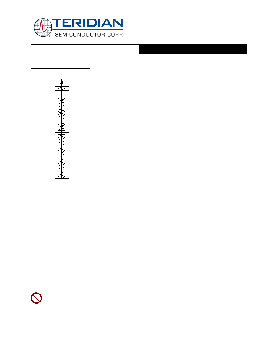
There is no internal digital state that deactivates the WDT. For debug purposes, however,
the WDT can be disabled by tying the V1 pin to V3P3 (see Figure 37). Of course, this also
deactivates V1 power fault detection. Since there is no method in firmware to disable the
crystal oscillator or the WDT, it is guaranteed that whatever state the part might find itself
in, upon WDT overflow, the part will be reset to a known state.
Asserting ICE_E will also deactivate the WDT. This is the only method that will disable the
WDT in BROWNOUT mode.
In normal operation, the WDT is reset by periodically writing a one to the WDT_RST bit. The
watchdog timer is also reset when the internal signal WAKE=0 (see section on Wake Up
Behavior).
Figure 14: Functions defined by V1
Program Security
When enabled, the security feature limits the ICE to global flash erase operations only. All other ICE operations are blocked.
This guarantees the security of the user’s MPU and CE program code. Security is enabled by MPU code that is executed in a
32 cycle preboot interval before the primary boot sequence begins. Once security is enabled, the only way to disable it is to
perform a global erase of the flash, followed by a chip reset.
The first 32 cycles of the MPU boot code are called the preboot phase because during this phase the ICE is inhibited. A read-
only status bit, PREBOOT, identifies these cycles to the MPU. Upon completion of preboot, the ICE can be enabled and is
permitted to take control of the MPU.
SECURE, the security enable bit, is reset whenever the chip is reset. Hardware associated with the bit permits only ones to be
written to it. Thus, preboot code may set SECURE to enable the security feature but may not reset it. Once SECURE is set, the
preboot code is protected and no external read of program code is possible
Specifically, when SECURE is set:
The ICE is limited to bulk flash erase only.
Page zero of flash memory, the preferred location for the user’s preboot code, may not be page-erased by either
MPU or ICE. Page zero may only be erased with global flash erase.
Writes to page zero, whether by MPU or ICE are inhibited.
The
SECURE bit is to be used with caution! Inadvertently setting this bit will inhibit access to the part via the ICE
interface, if no mechanism for actively resetting the part between reset and erase operations is provided (see ICE
Interface description).
V3P3
V3P3 -
400mV
V3P3 - 10mV
VBIAS
0V
Battery
modes
Normal
operation,
WDT
enabled
WDT dis-
abled
V1
相关PDF资料 |
PDF描述 |
|---|---|
| 71M6531D-IMR/F | 1-CHANNEL POWER SUPPLY MANAGEMENT CKT, QCC68 |
| 71M6532D-IGTR/F | 1-CHANNEL POWER SUPPLY MANAGEMENT CKT, PQFP100 |
| 71M6532F-IGT/F | 1-CHANNEL POWER SUPPLY MANAGEMENT CKT, PQFP100 |
| 71M6531D-IM/F | 1-CHANNEL POWER SUPPLY MANAGEMENT CKT, QCC68 |
| 71M6531F-IMR/F | 1-CHANNEL POWER SUPPLY MANAGEMENT CKT, QCC68 |
相关代理商/技术参数 |
参数描述 |
|---|---|
| 71M6521FE-IGTR | 制造商:Maxim Integrated Products 功能描述:Metering Systems on a Chip - SoC Residential Energy Meter IC |
| 71M6521FE-IGTR/F | 功能描述:计量片上系统 - SoC Residential Energy Meter IC RoHS:否 制造商:Maxim Integrated 核心:80515 MPU 处理器系列:71M6511 类型:Metering SoC 最大时钟频率:70 Hz 程序存储器大小:64 KB 数据 RAM 大小:7 KB 接口类型:UART 可编程输入/输出端数量:12 片上 ADC: 安装风格:SMD/SMT 封装 / 箱体:LQFP-64 封装:Reel |
| 71M6521FE-IGTR/F1 | 功能描述:计量片上系统 - SoC RoHS:否 制造商:Maxim Integrated 核心:80515 MPU 处理器系列:71M6511 类型:Metering SoC 最大时钟频率:70 Hz 程序存储器大小:64 KB 数据 RAM 大小:7 KB 接口类型:UART 可编程输入/输出端数量:12 片上 ADC: 安装风格:SMD/SMT 封装 / 箱体:LQFP-64 封装:Reel |
| 71M6521FE-IM | 制造商:Maxim Integrated Products 功能描述:Metering Systems on a Chip - SoC Residential Energy Meter IC |
| 71M6521FE-IM/F | 功能描述:计量片上系统 - SoC Residential Energy Meter IC RoHS:否 制造商:Maxim Integrated 核心:80515 MPU 处理器系列:71M6511 类型:Metering SoC 最大时钟频率:70 Hz 程序存储器大小:64 KB 数据 RAM 大小:7 KB 接口类型:UART 可编程输入/输出端数量:12 片上 ADC: 安装风格:SMD/SMT 封装 / 箱体:LQFP-64 封装:Reel |
发布紧急采购,3分钟左右您将得到回复。