- 您现在的位置:买卖IC网 > PDF目录68811 > 71M6521FE-IGT/F (MAXIM INTEGRATED PRODUCTS INC) SPECIALTY ANALOG CIRCUIT, QFP64 PDF资料下载
参数资料
| 型号: | 71M6521FE-IGT/F |
| 厂商: | MAXIM INTEGRATED PRODUCTS INC |
| 元件分类: | 模拟信号调理 |
| 英文描述: | SPECIALTY ANALOG CIRCUIT, QFP64 |
| 封装: | LEAD FREE, LQFP-64 |
| 文件页数: | 7/103页 |
| 文件大小: | 1691K |
| 代理商: | 71M6521FE-IGT/F |
第1页第2页第3页第4页第5页第6页当前第7页第8页第9页第10页第11页第12页第13页第14页第15页第16页第17页第18页第19页第20页第21页第22页第23页第24页第25页第26页第27页第28页第29页第30页第31页第32页第33页第34页第35页第36页第37页第38页第39页第40页第41页第42页第43页第44页第45页第46页第47页第48页第49页第50页第51页第52页第53页第54页第55页第56页第57页第58页第59页第60页第61页第62页第63页第64页第65页第66页第67页第68页第69页第70页第71页第72页第73页第74页第75页第76页第77页第78页第79页第80页第81页第82页第83页第84页第85页第86页第87页第88页第89页第90页第91页第92页第93页第94页第95页第96页第97页第98页第99页第100页第101页第102页第103页
71M6521DE/71M6521FE
Energy Meter IC
DATA SHEET
OCTOBER 2010
v1.1
2005-2010 Teridian Semiconductor Corporation
Page: 11 of 103
A Maxim Integrated Products Brand
19-5370; 10/10
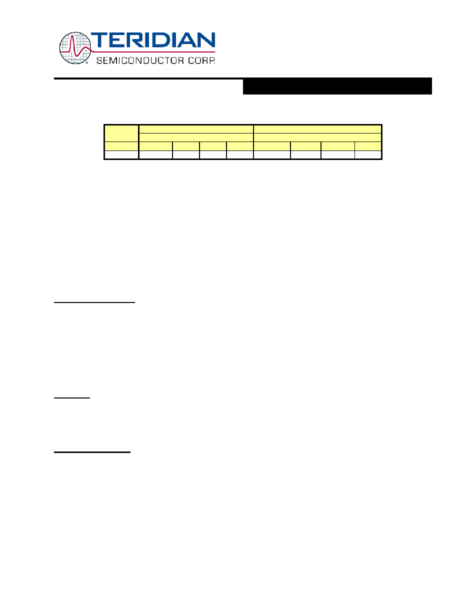
Regular MUX Sequence
ALT MUX Sequence
Mux State
EQU
0
1
2
3
0
1
2
3
0, 1, 2
IA
VA
IB
VB
TEMP
VA
IB
VBAT
Table 1: Inputs Selected in Regular and Alternate Multiplexer Cycles
In a typical application, IA and IB are connected to current transformers that sense the current on each phase of the line
voltage. VA and VB are typically connected to voltage sensors through resistor dividers.
The multiplexer control circuit handles the setting of the multiplexer. The function of the control circuit is governed by the I/O
RAM registers MUX_ALT, MUX_DIV and EQU. MUX_DIV controls the number of samples per cycle. It can request 2, 3, or 4
multiplexer states per cycle. Multiplexer states above 4 are reserved and must not be used. The multiplexer always starts at
the beginning of its list and proceeds until MUX_DIV states have been converted.
The MUX_ALT bit requests an alternative multiplexer frame. The bit may be asserted on any MPU cycle and may be
subsequently de-asserted on any cycle including the next one. A rising edge on MUX_ALT will cause the multiplexer control
circuit to wait until the next multiplexer cycle and implement a single alternate cycle.
The multiplexer control circuit also controls the FIR filter initiation and the chopping of the ADC reference voltage, VREF. The
multiplexer control circuit is clocked by CK32, the 32768Hz clock from the PLL block, and launches with each new pass of the
CE program.
A/D Converter (ADC)
A single delta-sigma A/D converter digitizes the voltage and current inputs to the 71M6521DE/FE. The resolution of the ADC is
programmable using the FIR_LEN register as shown in the I/O RAM section. ADC resolution can be selected to be 21 bits
(FIR_LEN=0), or 22 bits (FIR_LEN=1). Conversion time is two cycles of CK32 with FIR_LEN = 0 and three cycles with FIR_LEN
= 1.
In order to provide the maximum resolution, the ADC should be operated with FIR_LEN = 1. Accuracy and timing
specifications in this data sheet are based on FIR_LEN = 1.
Initiation of each ADC conversion is controlled by the multiplexer control circuit as described previously. At the end of each
ADC conversion, the FIR filter output data is stored into the CE DRAM location determined by the multiplexer selection.
FIR Filter
The finite impulse response filter is an integral part of the ADC and it is optimized for use with the multiplexer. The purpose of
the FIR filter is to decimate the ADC output to the desired resolution. At the end of each ADC conversion, the output data is
stored into the fixed CE DRAM location determined by the multiplexer selection. FIR data is stored LSB justified, but shifted left
by nine bits.
Voltage References
The device includes an on-chip precision bandgap voltage reference that incorporates auto-zero techniques. The reference is
trimmed to minimize errors caused by component mismatch and drift. The result is a voltage output with a predictable
temperature coefficient.
The amplifier within the reference is chopper stabilized, i.e. the polarity can be switched by the MPU using the I/O RAM
register CHOP_E (0x2002[5:4]). The two bits in the CHOP_E register enable the MPU to operate the chopper circuit in regular
or inverted operation, or in “toggling” mode. When the chopper circuit is toggled in between multiplexer cycles, DC offsets on
the measured signals will automatically be averaged out.
The general topology of a chopped amplifier is given in Figure 2.
相关PDF资料 |
PDF描述 |
|---|---|
| 71M6531D-IMR/F | 1-CHANNEL POWER SUPPLY MANAGEMENT CKT, QCC68 |
| 71M6532D-IGTR/F | 1-CHANNEL POWER SUPPLY MANAGEMENT CKT, PQFP100 |
| 71M6532F-IGT/F | 1-CHANNEL POWER SUPPLY MANAGEMENT CKT, PQFP100 |
| 71M6531D-IM/F | 1-CHANNEL POWER SUPPLY MANAGEMENT CKT, QCC68 |
| 71M6531F-IMR/F | 1-CHANNEL POWER SUPPLY MANAGEMENT CKT, QCC68 |
相关代理商/技术参数 |
参数描述 |
|---|---|
| 71M6521FE-IGTR | 制造商:Maxim Integrated Products 功能描述:Metering Systems on a Chip - SoC Residential Energy Meter IC |
| 71M6521FE-IGTR/F | 功能描述:计量片上系统 - SoC Residential Energy Meter IC RoHS:否 制造商:Maxim Integrated 核心:80515 MPU 处理器系列:71M6511 类型:Metering SoC 最大时钟频率:70 Hz 程序存储器大小:64 KB 数据 RAM 大小:7 KB 接口类型:UART 可编程输入/输出端数量:12 片上 ADC: 安装风格:SMD/SMT 封装 / 箱体:LQFP-64 封装:Reel |
| 71M6521FE-IGTR/F1 | 功能描述:计量片上系统 - SoC RoHS:否 制造商:Maxim Integrated 核心:80515 MPU 处理器系列:71M6511 类型:Metering SoC 最大时钟频率:70 Hz 程序存储器大小:64 KB 数据 RAM 大小:7 KB 接口类型:UART 可编程输入/输出端数量:12 片上 ADC: 安装风格:SMD/SMT 封装 / 箱体:LQFP-64 封装:Reel |
| 71M6521FE-IM | 制造商:Maxim Integrated Products 功能描述:Metering Systems on a Chip - SoC Residential Energy Meter IC |
| 71M6521FE-IM/F | 功能描述:计量片上系统 - SoC Residential Energy Meter IC RoHS:否 制造商:Maxim Integrated 核心:80515 MPU 处理器系列:71M6511 类型:Metering SoC 最大时钟频率:70 Hz 程序存储器大小:64 KB 数据 RAM 大小:7 KB 接口类型:UART 可编程输入/输出端数量:12 片上 ADC: 安装风格:SMD/SMT 封装 / 箱体:LQFP-64 封装:Reel |
发布紧急采购,3分钟左右您将得到回复。