- 您现在的位置:买卖IC网 > PDF目录21914 > A1351KKTTN-T (Allegro Microsystems Inc)IC SENSOR HALL EFFECT 4-SIP PDF资料下载
参数资料
| 型号: | A1351KKTTN-T |
| 厂商: | Allegro Microsystems Inc |
| 文件页数: | 17/24页 |
| 文件大小: | 663K |
| 描述: | IC SENSOR HALL EFFECT 4-SIP |
| 产品培训模块: | Current Sensor |
| 产品变化通告: | Product Obsolescence 09/Nov/2011 |
| 标准包装: | 4,000 |
| 传感范围: | 0.055% ~ 0.095% DC/G |
| 类型: | 线性 - 单极,双极 |
| 电源电压: | 4.5 V ~ 5.5 V |
| 电流 - 电源: | 10mA |
| 电流 - 输出(最大): | 1mA |
| 输出类型: | 数字,推挽式 |
| 特点: | 高精度 |
| 工作温度: | -40°C ~ 125°C |
| 封装/外壳: | 4-SIP |
| 供应商设备封装: | 4-SIP |
| 包装: | 带卷 (TR) |
A1351
High Precision Linear Hall Effect Sensor IC
with a Push/Pull, Pulse Width Modulated Output
16
Allegro MicroSystems, Inc.
115 Northeast Cutoff
Worcester, Massachusetts 01615-0036 U.S.A.
1.508.853.5000; www.allegromicro.com
Parameter Selection
Each of the five programmable parameters can be accessed
through its corresponding parameter register. There is also a
LOCK register. These registers and their parameters are:
Register 1:
" Sensitivity, Sens
" Coarse quiescent duty cycle, D
(Q)
Register 2:
" Quiescent duty cycle output, D
(Q)
Register 3:
" PWM carrier frequency, f
PWM
" Calibration test mode
Register 5:
" Overall device locking, LOCK
To select a register, a sequence of one V
PH
pulse, the key for the
register, and a second V
PH
pulse (with no VCC supply interrup-
tions) must be applied serially to the PWMOUT pin. The pulse
train used for selection of the first register, key 1, is shown in
figure 1.
V+
0
t
LOW
t
ACTIVE
V
P(HIGH)
V
P(MID)
V
P(LOW)
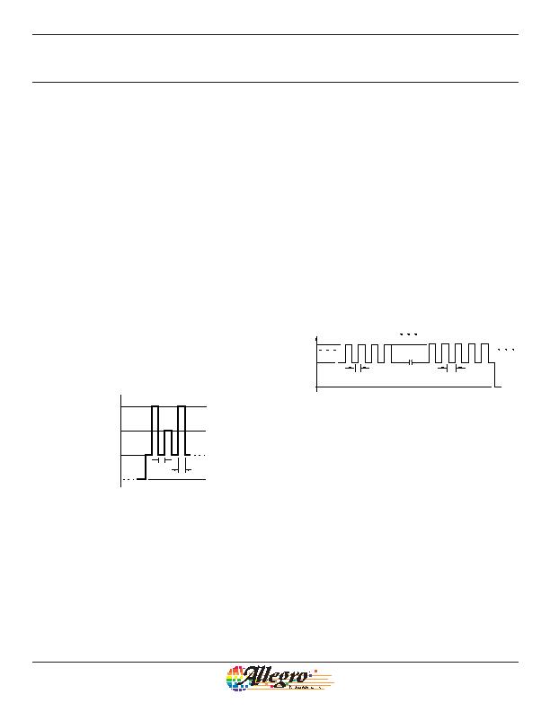
Figure 1. Parameter selection pulse train. This shows the sequence for
selecting the register corresponding to key 1, indicated by a single V
PM
pulse.
After the falling edge of the second V
PH
pulse, the selected regis-
ter bit field may be addressed with the appropriate code (see Bit
Field Addressing section, below).
Bit Field Addressing
After the register of a programmable parameter has been selected
as described above, the code pulses must be applied serially to
the PWMOUT pin with no VCC supply interruptions. As each
additional pulse in the code is transmitted, the overall setting of
the bit field increments by 1, up to the maximum possible code
for that register (see the Programming Logic table). The A1351
logic interprets the overall setting (the binary sum of all of the
activated or blown fuses) and applies it to the value of the param-
eter, according to the step size for the parameter (shown in the
Electrical Characteristics table).
Addressing activates the corresponding fuse locations in the
given bit field by incrementing the binary value of an internal
DAC. Measurements can be taken after each pulse to determine
if the desired result for the programmable parameter has been
reached. Cycling the supply voltage resets all the locations in the
bit field that have unblown fuses to their initial states.
t
LOW
t
ACTIVE
V
P(MID)
V
P(LOW)
V+
0
Figure 2. Bit eld addressing pulse train. Addressing the bit eld by incre-
menting the code causes the programmable parameter value to change.
The number of bits available for a given programming code, n, varies
among parameters; for example, the bit eld for Sensitivity has 8 bits avail-
able, which allows 255 separate codes to be used.
Fuse Blowing
After the required code is found for a given parameter, its value
can be set permanently by blowing individual fuses in the appro-
priate register bit field. Blowing is accomplished by applying a
high voltage pulse, called a blow pulse, of sufficient duration to
permanently set an addressed bit by blowing a fuse internal to the
device. Due to power requirements, the fuse for each bit in the
bit field must be blown individually. To accomplish this, the code
representing the desired parameter value must be translated to a
binary number. For example, as shown in figure 3, decimal code
5 is equivalent to the binary number 101. Therefore bit 2 (code
4) must be addressed and blown, the device power supply cycled,
and then bit 0 (code 1) addressed and blown. The order of blow-
ing bits, however, is not important. Blowing bit 0 first, and then
bit 2, is acceptable.
Programming Procedures
相关PDF资料 |
PDF描述 |
|---|---|
| 3864-48 | CORD DBL BANANA PLUG COILED 48" |
| DMN3029LFG-13 | MOSFET N-CH 30V 5.3A PWRDI333-8 |
| 2239-C-48 | MULTI-STACK BANANA PLUG RG58 48" |
| A1186LLHLT-T | IC SWITCH HALL EFFECT UNI SOT-23 |
| A1186EUA-T | IC SWITCH HALL EFFECT UNI 3-SIP |
相关代理商/技术参数 |
参数描述 |
|---|---|
| A1351LKTTN-T | 功能描述:IC SENSOR HALL EFFECT 4-SIP RoHS:是 类别:传感器,转换器 >> 磁性 - 霍尔效应,数字式开关,线性,罗盘 (IC) 系列:- 标准包装:1 系列:- 传感范围:20mT ~ 80mT 类型:旋转 电源电压:4.5 V ~ 5.5 V 电流 - 电源:15mA 电流 - 输出(最大):- 输出类型:数字式,PWM,8.5 位串行 特点:可编程 工作温度:-40°C ~ 150°C 封装/外壳:20-SSOP(0.209",5.30mm 宽) 供应商设备封装:20-SSOP 包装:Digi-Reel® 其它名称:AS5132-HSST-500DKR |
| A1352-035 | 制造商:AVX Corporation 功能描述: |
| A1352-037 | 制造商:AVX Corporation 功能描述: |
| A13532-43N | 制造商:Harris Corporation 功能描述: |
| A1354 | 制造商:ALLEGRO 制造商全称:Allegro MicroSystems 功能描述:High Precision 2-Wire Linear Hall Effect Sensor IC with Pulse Width Modulated Output |
发布紧急采购,3分钟左右您将得到回复。