参数资料
| 型号: | AD5934YRSZ |
| 厂商: | Analog Devices Inc |
| 文件页数: | 10/32页 |
| 文件大小: | 0K |
| 描述: | IC NTWK ANALYZER 12B 1MSP 16SSOP |
| 产品培训模块: | Direct Digital Synthesis Tutorial Series (1 of 7): Introduction Direct Digital Synthesizer Tutorial Series (7 of 7): DDS in Action Direct Digital Synthesis Tutorial Series (3 of 7): Angle to Amplitude Converter Direct Digital Synthesis Tutorial Series (6 of 7): SINC Envelope Correction Direct Digital Synthesis Tutorial Series (4 of 7): Digital-to-Analog Converter Direct Digital Synthesis Tutorial Series (2 of 7): The Accumulator |
| 标准包装: | 1 |
| 分辨率(位): | 12 b |
| 主 fclk: | 16.776MHz |
| 电源电压: | 2.7 V ~ 5.5 V |
| 工作温度: | -40°C ~ 125°C |
| 安装类型: | 表面贴装 |
| 封装/外壳: | 16-SSOP(0.209",5.30mm 宽) |
| 供应商设备封装: | 16-SSOP |
| 包装: | 管件 |
| 产品目录页面: | 797 (CN2011-ZH PDF) |
| 配用: | EVAL-AD5934EBZ-ND - BOARD EVALUATION FOR AD5934 |
第1页第2页第3页第4页第5页第6页第7页第8页第9页当前第10页第11页第12页第13页第14页第15页第16页第17页第18页第19页第20页第21页第22页第23页第24页第25页第26页第27页第28页第29页第30页第31页第32页
AD5934
Data Sheet
Rev. C | Page 18 of 32
Note that it is possible to calculate the gain factor and to calibrate
the system phase using the same real and imaginary component
values when a resistor is connected between the VOUT and
VIN pins of the AD5934, for example, measuring the impedance
phase (Z) of a capacitor.
The excitation signal current leads the excitation signal voltage
across a capacitor by 90 degrees. Therefore, an approximate
90 degrees phase difference between the system phase responses
measured with a resistor and the system phase responses measured
with a capacitive impedance exists.
As previously outlined, if the user wants to determine the phase
angle of the capacitive impedance (Z), the user first must
determine the system phase response ( system
) and subtract
this from the phase calculated with the capacitor connected
between VOUT and VIN (Φunknown).
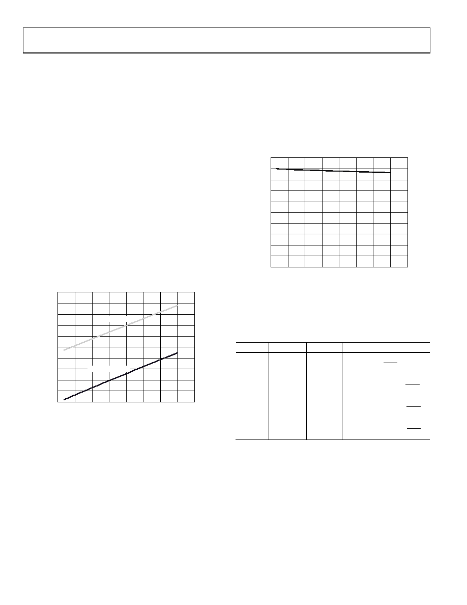
Figure 22 shows the AD5934 system phase response calculated
using a 220 k calibration resistor (RFB = 220 kΩ, PGA = ×1)
and the repeated phase measurement with a 10 pF capacitive
impedance.
One important point to note about the phase formula used to
plot Figure 22 is that it uses the arctangent function that returns
a phase angle in radians and, therefore, it is necessary to convert
from radians to degrees.
0
20
40
60
80
100
120
140
160
180
200
SYST
EM
PH
A
SE
(D
e
g
re
e
s
)
60k
45k
15k
30k
0
75k
90k
105k
120k
FREQUENCY (Hz)
05325-
090
220
k RESISTOR
10pF CAPACITOR
Figure 22. System Phase Response vs. Capacitive Phase
The phase difference (that is, Z) between the phase response
of a capacitor and the system phase response using a resistor is
the impedance phase of the capacitor (Z) and is shown in
In addition, when using the real and imaginary values to interpret
the phase at each measurement point, care should be taken
when using the arctangent formula. The arctangent function
only returns the correct standard phase angle when the sign of
the real and imaginary values are positive, that is, when the
coordinates lie in the first quadrant. The standard angle is
taken counterclockwise from the positive real x-axis. If the sign
of the real component is positive and the sign of the imaginary
component is negative, that is, the data lies in the second
quadrant, the arctangent formula returns a negative angle, and
it is necessary to add an additional 180° to calculate the correct
standard angle. Likewise, when the real and imaginary components
are both negative, that is, when data lies in the third quadrant,
the arctangent formula returns a positive angle, and it is necessary
to add an additional 180° to calculate the correct standard
phase. When the real component is positive and the imaginary
component is negative, that is, the data lies in the fourth quadrant,
the arctangent formula returns a negative angle, and it is necessary
to add an additional 360° to calculate the correct standard phase.
P
HAS
E
(
Deg
rees)
60k
45k
15k
30k
0
75k
90k
105k
120k
FREQUENCY (Hz)
05325-
091
–100
–90
–80
–70
–60
–50
–40
–30
–20
–10
0
Figure 23. Phase Response of a Capacitor
Therefore, the correct standard phase angle is dependent
upon the sign of the real and imaginary components, which is
summarized in Table 6.
Table 6. Phase Angle
Real
Imaginary
Quadrant
Phase Angle
Positive
First
π
°
×
180
)
/
(
tan 1 R
I
Positive
Negative
Second
π
°
×
+
°
180
)
/
(
tan
180
1
R
I
Negative
Third
π
°
×
+
°
180
)
/
(
tan
180
1
R
I
Negative
Positive
Fourth
π
°
×
+
°
180
)
/
(
tan
360
1
R
I
Once the magnitude of the impedance (|Z|) and the impedance
phase angle (Z, in radians) are correctly calculated, it is possible
to determine the magnitude of the real (resistive) and imaginary
(reactive) components of the impedance (ZUNKNOWN) by the vector
projection of the impedance magnitude onto the real and
imaginary impedance axis using the following formulas:
The real component is given by
|ZREAL| = |Z| × cos(Z)
The imaginary component is given by
|ZIMAG| = |Z| × sin(Z)
相关PDF资料 |
PDF描述 |
|---|---|
| AD598JR | IC LVDT SGNL COND OSC/REF 20SOIC |
| AD660BR | IC DAC 16BIT MONO W/VREF 24-SOIC |
| AD6620ASZ | IC DGTL RCVR DUAL 67MSPS 80-PQFP |
| AD6623ASZ | IC TSP 4CHAN 104MSPS 128MQFP |
| AD6641BCPZRL7-500 | IC IF RCVR 11BIT 200MSPS 56LFCSP |
相关代理商/技术参数 |
参数描述 |
|---|---|
| AD5934YRSZ-REEL7 | 功能描述:IC CONV 12BIT 250KSPS 16SSOP RoHS:是 类别:集成电路 (IC) >> 接口 - 直接数字合成 (DDS) 系列:- 产品变化通告:Product Discontinuance 27/Oct/2011 标准包装:2,500 系列:- 分辨率(位):10 b 主 fclk:25MHz 调节字宽(位):32 b 电源电压:2.97 V ~ 5.5 V 工作温度:-40°C ~ 85°C 安装类型:表面贴装 封装/外壳:16-TSSOP(0.173",4.40mm 宽) 供应商设备封装:16-TSSOP 包装:带卷 (TR) |
| AD594 | 制造商:AD 制造商全称:Analog Devices 功能描述:Monolithic Thermocouple Amplifiers with Cold Junction Compensation |
| AD594A | 制造商:AD 制造商全称:Analog Devices 功能描述:Monolithic Thermocouple Amplifiers with Cold Junction Compensation |
| AD594AD | 制造商:Analog Devices 功能描述:Temp Sensor Analog 14-Pin TO-116 制造商:Rochester Electronics LLC 功能描述:THERMOCOUPLER AMPLIFIER - Bulk 制造商:Analog Devices 功能描述:Special Function IC Package/Case:TO-116 |
| AD594AD/+ | 制造商:Rochester Electronics LLC 功能描述:- Bulk |
发布紧急采购,3分钟左右您将得到回复。