参数资料
| 型号: | AD9912ABCPZ |
| 厂商: | Analog Devices Inc |
| 文件页数: | 16/40页 |
| 文件大小: | 0K |
| 描述: | IC DDS 1GSPS DAC 14BIT 64LFCSP |
| 产品培训模块: | Direct Digital Synthesis Tutorial Series (1 of 7): Introduction Direct Digital Synthesizer Tutorial Series (7 of 7): DDS in Action Direct Digital Synthesis Tutorial Series (3 of 7): Angle to Amplitude Converter Direct Digital Synthesis Tutorial Series (6 of 7): SINC Envelope Correction Direct Digital Synthesis Tutorial Series (4 of 7): Digital-to-Analog Converter Direct Digital Synthesis Tutorial Series (2 of 7): The Accumulator |
| 标准包装: | 1 |
| 分辨率(位): | 14 b |
| 主 fclk: | 1GHz |
| 调节字宽(位): | 48 b |
| 电源电压: | 1.8V, 3.3V |
| 工作温度: | -40°C ~ 85°C |
| 安装类型: | 表面贴装 |
| 封装/外壳: | 64-VFQFN 裸露焊盘,CSP |
| 供应商设备封装: | 64-LFCSP-VQ(9x9) |
| 包装: | 托盘 |
第1页第2页第3页第4页第5页第6页第7页第8页第9页第10页第11页第12页第13页第14页第15页当前第16页第17页第18页第19页第20页第21页第22页第23页第24页第25页第26页第27页第28页第29页第30页第31页第32页第33页第34页第35页第36页第37页第38页第39页第40页
AD9912
Rev. F | Page 23 of 40
The procedure for tuning the spur reduction is as follows:
Although the worst spurs tend to be harmonic in origin, the fact
that the DAC is part of a sampled system results in the possibility
of spurs appearing in the output spectrum that are not harmoni-
cally related to the fundamental. For example, if the DAC is
sampled at 1 GHz and generates an output sinusoid of 170 MHz,
the fifth harmonic would normally be at 850 MHz. However,
because of the sampling process, this spur appears at 150 MHz,
only 20 MHz away from the fundamental. Therefore, when
attempting to reduce DAC spurs it is important to know the
actual location of the harmonic spur in the DAC output
spectrum based on the DAC sample rate so that its harmonic
number can be reduced.
1.
Determine which offending harmonic spur to reduce and
its amplitude. Enter that harmonic number into Bit 0 to
Bit 3 of Register 0x0500/Register 0x0505.
2.
Turn off the fundamental by setting Bit 7 of Register 0x0013
and enable the SpurKiller channel by setting Bit 7 of
Register 0x0500/Register 0x0505.
3.
Adjust the amplitude of the SpurKiller channel so that it
matches the amplitude of the offending spur.
4.
Turn the fundamental on by clearing Bit 7 of Register 0x0013.
5.
Adjust the phase of the SpurKiller channel so that
maximum interference is achieved.
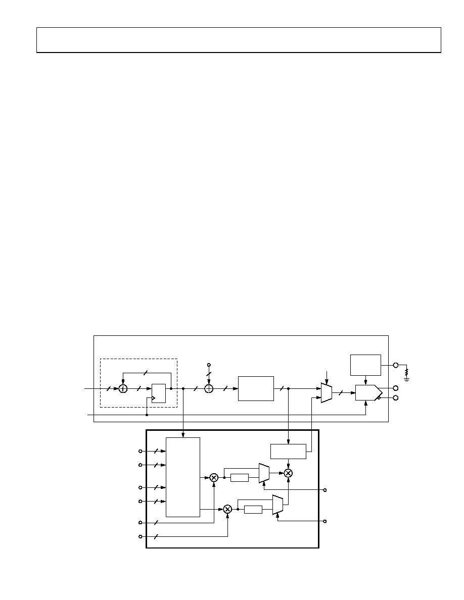
The mechanics of performing harmonic spur reduction is shown
in Figure 48. It essentially consists of two additional DDS cores
operating in parallel with the original DDS. This enables the user
to reduce two different harmonic spurs from the second to the
15th with nine bits of phase offset control (±π) and eight bits of
amplitude control.
Note that the SpurKiller setting is sensitive to the loading of the
DAC output pins, and that a DDS reset is required if a SpurKiller
channel is turned off. The DDS can be reset by setting Bit 0 of
Register 0x0012, and resetting the part is not necessary.
The performance improvement offered by this technique varies
widely and depends on the conditions used. Given this extreme
variability, it is impossible to define a meaningful specification
to guarantee SpurKiller performance. Current data indicate that
a 6 dB to 8 dB improvement is possible for a given output
frequency using a common setting over process, temperature,
and voltage. There are frequencies, however, where a common
setting can result in much greater improvement. Manually
adjusting the SpurKiller settings on individual parts can result
in more than 30 dB of spurious performance improvement.
The dynamic range of the cancellation signal is further aug-
mented by a gain bit associated with each channel. When this
bit is set, the magnitude of the cancellation signal is doubled by
employing a 1-bit left-shift of the data. However, the shift
operation reduces the granularity of the cancellation signal
magnitude. The full-scale amplitude of a cancellation spur is
approximately 60 dBc when the gain bit is a Logic 0 and
approximately 54 dBc when the gain bit is a Logic 1.
06
76
3-
04
0
0
1
0
14
19
Q
D
48
14
DAC
(14-BIT)
DAC_OUT
DAC_OUTB
4
9
4
9
8
SHIFT
1
0
SHIFT
HEADROOM
CORRECTION
HARMONIC SPUR CANCELLATION
CH1 HARMONIC NUMBER
CH1 CANCELLATION PHASE OFFSET
CH2 HARMONIC NUMBER
CH2 CANCELLATION PHASE OFFSET
CH1 CANCELLATION MAGNITUDE
CH2 CANCELLATION MAGNITUDE
CH1 GAIN
CH2 GAIN
SPUR
CANCELLATION
ENABLE
ANGLE TO
AMPLITUDE
CONVERSION
DDS
PHASE
OFFSET
14
48
48-BIT ACCUMULATOR
DDS
48-BIT
FREQUENCY
TURNING WORD
(FTW)
SYSCLK
2-CHANNEL
HARMONIC
FREQUENCY
GENERATOR
CH1
CH2
DAC_RSET
DAC I-SET
REGISTERS
AND LOGIC
Figure 48. Spur Reduction Circuit Diagram
相关PDF资料 |
PDF描述 |
|---|---|
| AD9913BCPZ-REEL7 | IC DDS 250MSPS 10BIT ADC 32LFCSP |
| AD9923ABBCZ | IC PROCESSOR CCD 12BIT 105CSPBGA |
| AD9942BBCZ | IC PROCESSOR SGNL 14B 100CSPBGA |
| AD9944KCPZRL | IC CCD SIGNAL PROCESSOR 32-LFCSP |
| AD9945KCPZRL7 | IC CCD SIGNAL PROCESSOR 32-LFCSP |
相关代理商/技术参数 |
参数描述 |
|---|---|
| AD9912ABCPZ-REEL7 | 功能描述:IC DDS 1GSPS DAC 14BIT 64LFCSP RoHS:是 类别:集成电路 (IC) >> 接口 - 直接数字合成 (DDS) 系列:- 产品变化通告:Product Discontinuance 27/Oct/2011 标准包装:2,500 系列:- 分辨率(位):10 b 主 fclk:25MHz 调节字宽(位):32 b 电源电压:2.97 V ~ 5.5 V 工作温度:-40°C ~ 85°C 安装类型:表面贴装 封装/外壳:16-TSSOP(0.173",4.40mm 宽) 供应商设备封装:16-TSSOP 包装:带卷 (TR) |
| AD9912BCPZ | 制造商:Analog Devices 功能描述:Direct Digital Synthesizer 1000MHz 1-DAC 14-Bit Serial 64-Pin LFCSP EP 制造商:Analog Devices 功能描述:DIRECT DGTL SYNTHESIZER 64LFCSP EP - Trays 制造商:Analog Devices 功能描述:IC DDS 1GSPS 14BIT DAC |
| AD9912BCPZ-REEL7 | 制造商:Analog Devices 功能描述:DIRECT DGTL SYNTHESIZER 64LFCSP EP - Tape and Reel |
| AD9913 | 制造商:AD 制造商全称:Analog Devices 功能描述:Low Power 250 MSPS 10-Bit DAC 1.8 V CMOS Direct Digital Synthesizer |
| AD9913/PCBZ | 功能描述:数据转换 IC 开发工具 Sub 50mW 250MSPS (+) 10-bit DDS RoHS:否 制造商:Texas Instruments 产品:Demonstration Kits 类型:ADC 工具用于评估:ADS130E08 接口类型:SPI 工作电源电压:- 6 V to + 6 V |
发布紧急采购,3分钟左右您将得到回复。