- 您现在的位置:买卖IC网 > PDF目录17040 > ADS1259EVM (Texas Instruments)EVAL MODULE FOR ADS1259 PDF资料下载
参数资料
| 型号: | ADS1259EVM |
| 厂商: | Texas Instruments |
| 文件页数: | 6/48页 |
| 文件大小: | 0K |
| 描述: | EVAL MODULE FOR ADS1259 |
| 标准包装: | 1 |
| ADC 的数量: | 1 |
| 位数: | 24 |
| 采样率(每秒): | 14k |
| 数据接口: | 串行,SPI? |
| 工作温度: | -40°C ~ 125°C |
| 已用 IC / 零件: | ADS1259 |
| 已供物品: | 板 |
| 其它名称: | 296-29312 ADS1259EVM-ND |
第1页第2页第3页第4页第5页当前第6页第7页第8页第9页第10页第11页第12页第13页第14页第15页第16页第17页第18页第19页第20页第21页第22页第23页第24页第25页第26页第27页第28页第29页第30页第31页第32页第33页第34页第35页第36页第37页第38页第39页第40页第41页第42页第43页第44页第45页第46页第47页第48页
f
MOD/2
FLAG
1.05V
REF
AINN
AINP
J
Q
IABSI
K
DataRead
Reset
AINP
AINN(%V
)
-
R
EF
FLAG
Bit
+105
-105
0
(Conversions)
0
1
SBAS424D
– JUNE 2009 – REVISED AUGUST 2011
MODULATOR OVERLOAD BEHAVIOR
ADS1259 recovers as normal. Note that the linear
input range is
±100mV beyond the analog supply
The ADS1259 modulator is inherently stable and
voltages; with input levels greater than this range,
therefore has predictable recovery behavior resulting
use care to limit the input current to 100mA peak
from an input overdrive condition. The modulator
transient (10mA continuous).
does not exhibit the self-resetting behavior of other
modulator types, which often results in unstable
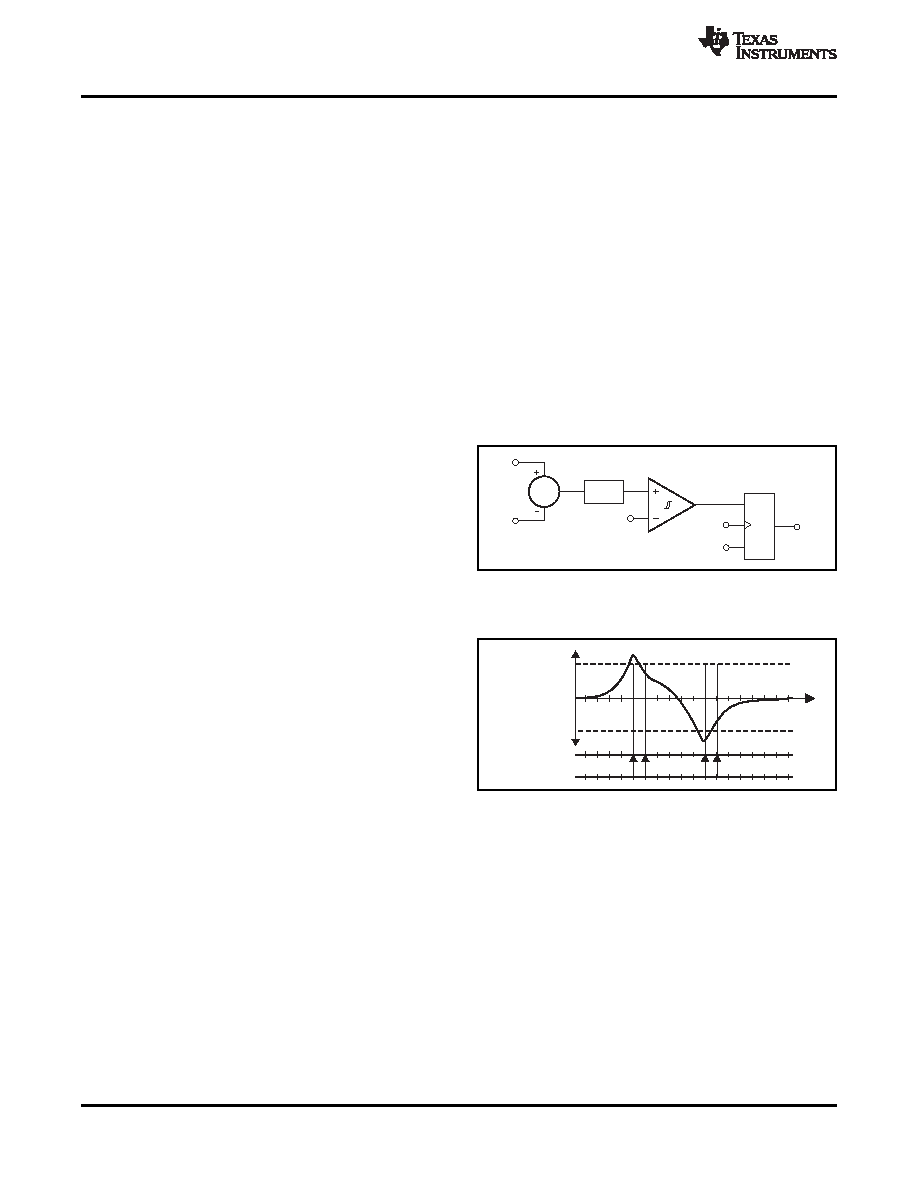
INPUT OUT-OF-RANGE DETECTION (FLAG)
output conversion results when overdriven.
The ADS1259 has a fast-responding out-of-range
The ADS1259 modulator outputs a 1s density data
circuit that triggers when the differential input exceeds
stream at 90% duty cycle with the positive full-scale
+105%
or
–105%
of
FSR
(
±1.05
VREF). The
input signal applied (10% duty cycle with the negative
out-of-range
circuit
latches
the
result
of
the
full-scale signal). If the input is overdriven past 90%
comparator output and appends the result as either
modulation, but below 100% modulation (10% and
the LSB of conversion data or as bit 7 of the data
0%
for
negative
overdrive,
respectively),
the
checksum byte. After the conversion data are read, or
modulator remains stable and continues to output the
after a new conversion is started, the comparator
1s density data stream. The digital filter may or may
not clip the output codes to +FS or
–FS, depending
detection block diagram and the detection operation,
on the duration of the overdrive. When the input is
respectively. See the Data Checksum Byte and FLAG
returned to the normal range from a long duration
Bit section for more detail.
overdrive
(worst
case),
the
modulator
returns
immediately to the normal range, but the group delay
of the digital filter delays the return of the conversion
result to within the linear range (one reading for the
sinc1 filter and two readings for completely settled
data).
If the inputs are sufficiently overdriven to drive the
modulator to full duty cycle (that is, all 1s or all 0s),
the modulator enters a stable saturated state. The
Figure 34. Input Out-Of-Range Detect Block
digital output code may clip to +FS or
–FS, again
Diagram
depending on the duration. A small duration overdrive
may not always clip the output code. When the input
returns to the normal range, the modulator requires
up to 12 modulator clock cycles (fMOD) to exit
saturation and return to the linear region. The digital
filter requires two additional conversions (sinc1, more
for sinc2) for fully settled data.
In the extreme case of over-range, either input is
overdriven
exceeding
that
either
analog
supply
voltage plus an internal ESD diode drop. The internal
ESD diodes begin to conduct and the signal on the
input is clipped. If the differential input signal range is
Figure 35. Input Out-Of-Range Detect Operation
not exceeded, the modulator remains in linear
operation. If the differential input signal range is
exceeded, the modulator is saturated but stable, and
outputs all 1s or 0s. When the input overdrive is
removed, the diodes recovery quickly and the
14
Copyright
2009–2011, Texas Instruments Incorporated
相关PDF资料 |
PDF描述 |
|---|---|
| 0210490281 | CABLE JUMPER 1.25MM .076M 22POS |
| EBC19DREN-S93 | CONN EDGECARD 38POS .100 EYELET |
| EEC19DRYN-S93 | CONN EDGECARD 38POS DIP .100 SLD |
| EBC19DREH-S93 | CONN EDGECARD 38POS .100 EYELET |
| MLK1005S2N4S | INDUCTOR MULTILAYER 2.4NH 0402 |
相关代理商/技术参数 |
参数描述 |
|---|---|
| ADS1259EVM | 制造商:Texas Instruments 功能描述:DEVELOPMENT TOOL |
| ADS1259EVM-PDK | 功能描述:数据转换 IC 开发工具 ADS1259 Perf Demo Kit RoHS:否 制造商:Texas Instruments 产品:Demonstration Kits 类型:ADC 工具用于评估:ADS130E08 接口类型:SPI 工作电源电压:- 6 V to + 6 V |
| ADS1259EVM-PDK | 制造商:Texas Instruments 功能描述:DEVELOPMENT TOOL |
| ADS1259IPW | 功能描述:模数转换器 - ADC Low-Noise 14kSPS 24B ADC RoHS:否 制造商:Texas Instruments 通道数量:2 结构:Sigma-Delta 转换速率:125 SPs to 8 KSPs 分辨率:24 bit 输入类型:Differential 信噪比:107 dB 接口类型:SPI 工作电源电压:1.7 V to 3.6 V, 2.7 V to 5.25 V 最大工作温度:+ 85 C 安装风格:SMD/SMT 封装 / 箱体:VQFN-32 |
| ADS1259IPW | 制造商:Texas Instruments 功能描述:A/D CONVERTER (A-D) IC |
发布紧急采购,3分钟左右您将得到回复。