- 您现在的位置:买卖IC网 > PDF目录171225 > DS1862AB+ (MAXIM INTEGRATED PRODUCTS INC) SPECIALTY CONSUMER CIRCUIT, PBGA25 PDF资料下载
参数资料
| 型号: | DS1862AB+ |
| 厂商: | MAXIM INTEGRATED PRODUCTS INC |
| 元件分类: | 消费家电 |
| 英文描述: | SPECIALTY CONSUMER CIRCUIT, PBGA25 |
| 封装: | 5 X 5 MM, ROHS COMPLIANT, CSBGA-25 |
| 文件页数: | 35/42页 |
| 文件大小: | 586K |
| 代理商: | DS1862AB+ |
第1页第2页第3页第4页第5页第6页第7页第8页第9页第10页第11页第12页第13页第14页第15页第16页第17页第18页第19页第20页第21页第22页第23页第24页第25页第26页第27页第28页第29页第30页第31页第32页第33页第34页当前第35页第36页第37页第38页第39页第40页第41页第42页
DS1862A
XFP Laser Control and Digital Diagnostic IC
40
______________________________________________________________________________________
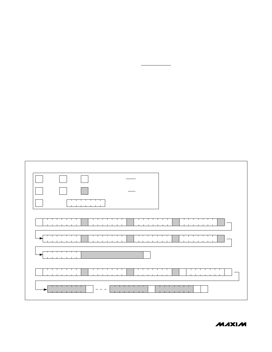
CRC-8 includes and requires the explicit starting mem-
ory address to be included as the second transferred
byte. Next, the master transfers the data as the
DS1862A acknowledges. Only 4 bytes can be sequen-
tially written during one transmission while using PEC.
After the master writes the intended number of bytes,
the CRC-8 value should be transmitted. Following the
CRC-8 byte, the master should transmit the CAB byte
(CRC Add-on Byte). At this point, the DS1862A sends
an ACK if the CRC-8 matches its internal calculated
value or a NACK if not. Finally, the master should end
the communication and send a STOP. See Figure 16 for
a graphical representation. The CRC-8 is calculated
starting with the MSB of the memory address pointer,
number of bytes to be written, and the written data. The
master can then poll the last ACK or NACK for suc-
cessful transfer of written data.
For more information on I2C PEC communications, refer
to the XFP and/or SMBus 2.0 standard.
Applications Information
Calibrating APC and Extinction Ratio
Before calibrating, the APC register should be set to a
low value to ensure the laser’s maximum power level is
not exceeded before the power level is calibrated.
Additionally, the ER should be set to a minimum value
to ensure that a data test pattern does not cause the
laser to shut off. Once the APC and ER registers are at
minimal values, enable a data pattern and calibrate the
average power level.
Calibrating the Average Power Level
While sending data through the laser diode, increase
the value in the APC register until the light output
matches the desired
average power level. The average
power level is the arithmetic average of the ‘1’ and ‘0’
power levels.
XXXXXXXX
10
1
0
10
1
0
10
1
0
COMMUNICATIONS KEY
WRITE UP TO A 4-BYTE PAGE WITH A SINGLE TRANSACTION USING PEC
READ 1–128 BYTES WITH A DUMMY WRITE CYCLE TO SET THE ADDRESS COUNTER
8-BIT ADDRESS OR DATA
WHITE BOXES INDICATE THE MASTER IS
CONTROLLING SDA
THE FIRST BYTE SENT AFTER A START CONDITION IS
ALWAYS THE SLAVE ADDRESS FOLLOWED BY THE
READ/WRITE BIT.
SHADED BOXES INDICATE THE SLAVE IS
CONTROLLING SDA
START
ACK
NOT
ACK
S
A
SR
A
N
P
A
CRC-8 VALUE
DATA
CRC-8 VALUE
DATA
MEMORY ADDRESS
A
NUMBER OF BYTES
MEMORY ADDRESS
DATA
AA
A
PN
SR
STOP
REPEATED
START
NOTE:
ALL BYTES ARE SENT MOST SIGNIFICANT BIT FIRST.
A (IF CRC-8 IS CORRECT)
P
DATA
Figure 16. I2C PEC Communications Examples
相关PDF资料 |
PDF描述 |
|---|---|
| DS1862AB+T&R | SPECIALTY CONSUMER CIRCUIT, PBGA25 |
| DS1868-100-IND | 100K DIGITAL POTENTIOMETER, 2-WIRE SERIAL CONTROL INTERFACE, 256 POSITIONS, PDIP14 |
| DS2-320-2AR | DIP20, IC SOCKET |
| DS1-314-1AR | DIP14, IC SOCKET |
| DS3-328-1AR | DIP28, IC SOCKET |
相关代理商/技术参数 |
参数描述 |
|---|---|
| DS1862AB+ | 功能描述:激光驱动器 XFP Laser Control & Digital Diagnostic RoHS:否 制造商:Micrel 数据速率:4.25 Gbps 工作电源电压:3 V to 3.6 V 电源电流:80 mA 最大工作温度:+ 85 C 封装 / 箱体:QFN-16 封装:Tube |
| DS1862AB+T&R | 制造商:Maxim Integrated Products 功能描述:XFP LASER CONTROL 25CSBGA - Tape and Reel 制造商:Maxim Integrated Products 功能描述:IC LASR CTRLR 7CHAN 5.5V 25CSBGA |
| DS1862AB+T&R | 功能描述:激光驱动器 XFP Laser Control & Digital Diagnostic RoHS:否 制造商:Micrel 数据速率:4.25 Gbps 工作电源电压:3 V to 3.6 V 电源电流:80 mA 最大工作温度:+ 85 C 封装 / 箱体:QFN-16 封装:Tube |
| DS1862AB+TR | 制造商:MAXIM 制造商全称:Maxim Integrated Products 功能描述:XFP Laser Control and Digital Diagnostic IC |
| DS1862B | 功能描述:激光驱动器 RoHS:否 制造商:Micrel 数据速率:4.25 Gbps 工作电源电压:3 V to 3.6 V 电源电流:80 mA 最大工作温度:+ 85 C 封装 / 箱体:QFN-16 封装:Tube |
发布紧急采购,3分钟左右您将得到回复。