- 您现在的位置:买卖IC网 > Datasheet目录222 > DS1923-F5# (Maxim Integrated)IBUTTON TEMP/HUMIDITY LOGGER F5 Datasheet资料下载
参数资料
| 型号: | DS1923-F5# |
| 厂商: | Maxim Integrated |
| 文件页数: | 4/55页 |
| 文件大小: | 0K |
| 描述: | IBUTTON TEMP/HUMIDITY LOGGER F5 |
| 产品培训模块: | Lead (SnPb) Finish for COTS Obsolescence Mitigation Program |
| RoHS指令信息: | IButton RoHS Compliance Plan |
| 标准包装: | 5 |
| 系列: | iButton® |
| 存储容量: | 512B |
| 存储器类型: | NVSRAM(非易失 SRAM) |
| 产品目录页面: | 1431 (CN2011-ZH PDF) |
第1页第2页第3页当前第4页第5页第6页第7页第8页第9页第10页第11页第12页第13页第14页第15页第16页第17页第18页第19页第20页第21页第22页第23页第24页第25页第26页第27页第28页第29页第30页第31页第32页第33页第34页第35页第36页第37页第38页第39页第40页第41页第42页第43页第44页第45页第46页第47页第48页第49页第50页第51页第52页第53页第54页第55页
�� �
�
�DS1923�
�iButton� Hygrochron� Temperature/Humidity�
�Logger� with� 8KB� Data-Log� Memory�
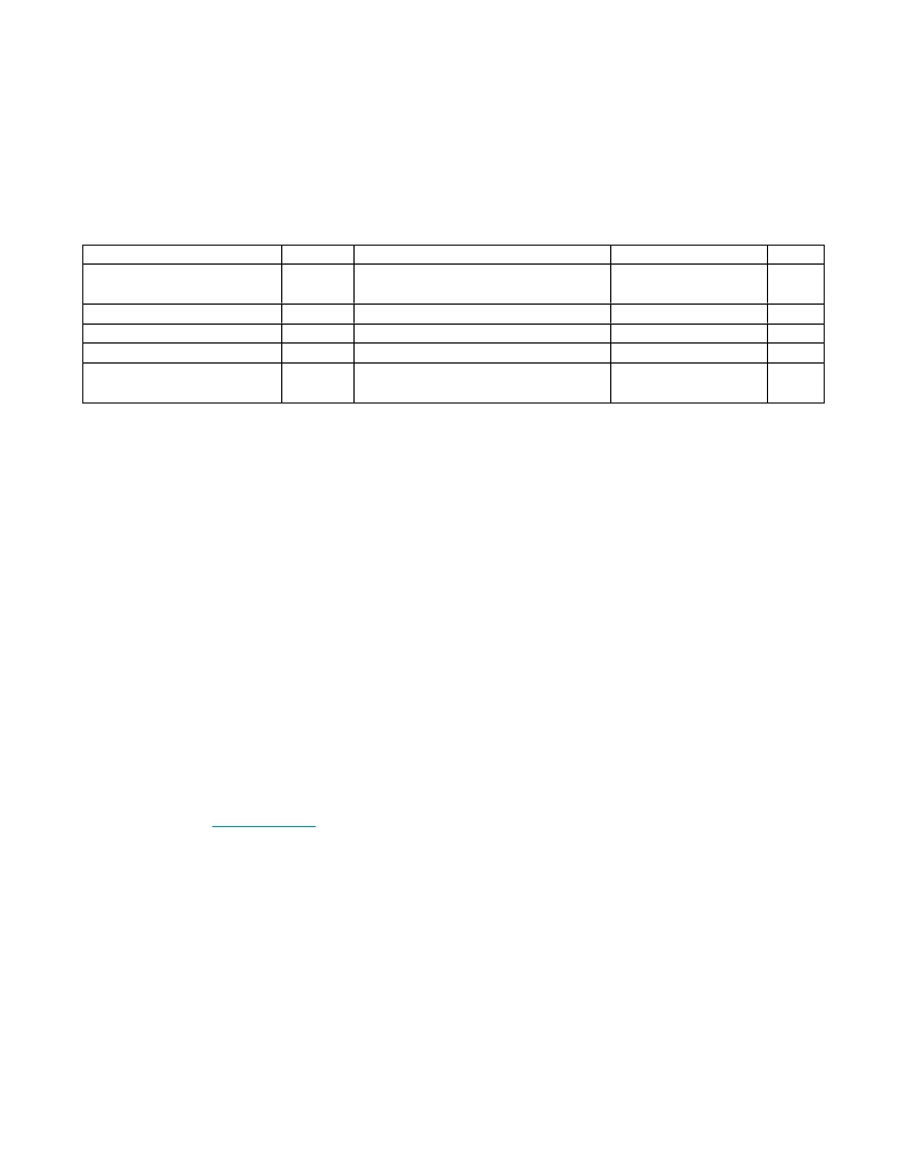
�ELECTRICAL� CHARACTERISTICS� (continued)�
�(V� PUP� =� +3.0V� to� +5.25V,� T� A� =� -20°C� to� +85°C.)� (Note� 31)�
�PARAMETER�
�SYMBOL�
�CONDITIONS�
�MIN�
�TYP�
�MAX�
�UNITS�
�RH� Accuracy� and�
�Interchangeability�
�RH� Nonlinearity�
�RH� Hysteresis�
�RH� Repeatability�
�Long-Term� Stability�
�With� software� correction�
�(Notes� 18,� 19,� 24,� 25,� 26)�
�With� software� correction� (Note� 18)�
�(Notes� 27,� 28)�
�(Note� 29)�
�At� 50%RH� (Note� 30)�
�±5�
�<1�
�0.5�
�±0.5�
�<� 1.0�
�%RH�
�%RH�
�%RH�
�%RH/�
�year�
�Note� 1:�
�Note� 2:�
�Note� 3:�
�Note� 4:�
�Note� 5:�
�Note� 6:�
�Note� 7:�
�Note� 8:�
�Note� 9:�
�Note� 10:�
�Note� 11:�
�Note� 12:�
�Note� 13:�
�Note� 14:�
�Note� 15:�
�Note� 16:�
�Note� 17:�
�Note� 18:�
�Note� 19:�
�Note� 20:�
�Note� 21:�
�Note� 22:�
�4�
�System� requirement.�
�Maximum� allowable� pullup� resistance� is� a� function� of� the� number� of� 1-Wire� devices� in� the� system� and� 1-Wire� recovery�
�times.� The� specified� value� here� applies� to� systems� with� only� one� device� and� with� the� minimum� 1-Wire� recovery� times.� For�
�more� heavily� loaded� systems,� an� active� pullup� such� as� that� in� the� DS2480B� may� be� required.�
�Capacitance� on� the� data� pin� could� be� 800pF� when� V� PUP� is� first� applied.� If� a� 2.2k� Ω� resistor� is� used� to� pull� up� the� data� line,�
�2.5μs� after� V� PUP� has� been� applied,� the� parasite� capacitance� does� not� affect� normal� communications.�
�V� TL� and� V� TH� are� functions� of� the� internal� supply� voltage,� which� is� a� function� of� V� PUP� and� the� 1-Wire� recovery� times.� The�
�V� TH� and� V� TL� maximum� specifications� are� valid� at� V� PUP� =� 5.25V.� In� any� case,� V� TL� <� V� TH� <� V� PUP� .�
�Voltage� below� which,� during� a� falling� edge� on� IO,� a� logic� 0� is� detected.�
�The� voltage� on� IO� must� be� less� than� or� equal� to� V� ILMAX� whenever� the� master� drives� the� line� low.�
�Voltage� above� which,� during� a� rising� edge� on� IO,� a� logic� 1� is� detected.�
�After� V� TH� is� crossed� during� a� rising� edge� on� IO,� the� voltage� on� IO� must� drop� by� V� HY� to� be� detected� as� logic� 0.�
�The� I-V� characteristic� is� linear� for� voltages� less� than� 1V.�
�The� earliest� recognition� of� a� negative� edge� is� possible� at� t� REH� after� V� TH� has� been� previously� reached.�
�Numbers� in� bold� are� not� in� compliance� with� the� published� iButton� device� standards.� See� the� Comparison� Table.�
�Interval� during� the� negative� edge� on� IO� at� the� beginning� of� a� presence-detect� pulse� between� the� time� at� which� the� voltage�
�is� 90%� of� V� PUP� and� the� time� at� which� the� voltage� is� 10%� of� V� PUP� .�
�ε� in� Figure� 13� represents� the� time� required� for� the� pullup� circuitry� to� pull� the� voltage� on� IO� up� from� V� IL� to� V� TH� .� The� actual�
�maximum� duration� for� the� master� to� pull� the� line� low� is� t� W1LMAX� +� t� F� -� ε� and� t� W0LMAX� +� t� F� -� ε� ,� respectively.�
�δ� in� Figure� 13� represents� the� time� required� for� the� pullup� circuitry� to� pull� the� voltage� on� IO� up� from� V� IL� to� the� input� high�
�threshold� of� the� bus� master.� The� actual� maximum� duration� for� the� master� to� pull� the� line� low� is� t� RLMAX� +� t� F� .�
�To� conserve� battery� power,� use� 8-bit� temperature� logging� whenever� possible.�
�This� number� was� derived� from� a� test� conducted� by� Cemagref� in� Antony,� France,� in� July� 2000:�
�www.cemagref.fr/English/index.htm� Test� Report� No.� E42.�
�For� software-corrected� accuracy,� assume� correction� using� calibration� coefficients� with� calibration� equations� for� error�
�compensation.�
�Software� correction� for� humidity� and� temperature� is� handled� automatically� using� the� 1-Wire� Viewer� Software� package�
�available� at:� www.ibutton.com� .�
�Warning:� Maxim� data-logger� products� are� 100%� tested� and� calibrated� at� time� of� manufacture� to� ensure� that� they� meet� all�
�data� sheet� parameters,� including� temperature� and/or� humidity� accuracy.� As� with� any� sensor-based� product,� user� shall� be�
�responsible� for� occasionally� rechecking� the� temperature� and/or� humidity� accuracy� of� the� product� to� ensure� it� is� still� oper-�
�ating� properly.� Furthermore,� as� with� all� products� of� this� type,� when� deployed� in� the� field� and� subjected� to� handling,� harsh�
�environments,� or� other� hazards/use� conditions,� there� may� be� some� extremely� small� but� nonzero� logger� failure� rate.� In�
�applications� where� the� failure� of� any� logger� is� a� concern,� user� shall� assure� that� redundant� (or� other� primary)� methods� of�
�testing� and� determining� the� handling� methods,� quality,� and� fitness� of� the� articles� and� products� are� implemented� to� further�
�mitigate� any� risk.�
�All� humidity� specifications� are� determined� at� +25°C� except� where� specifically� indicated.�
�Response� time� is� determined� by� measuring� the� 1/e� point� as� the� device� transitions� from� 40%RH� to� 90%RH� or� 90%RH� to�
�40%RH,� whichever� is� slower.� Test� was� performed� at� 5L/min� airflow.�
�All� DS1923� humidity� measurements� are� 12-bit� readings.� Missioning� determines� 8-bit� or� 16-bit� data� logging.� Battery� life-�
�time� is� the� same� no� matter� what� RH� resolution� is� logged.�
�Maxim� Integrated�
�相关PDF资料 |
PDF描述 |
|---|---|
| DS1961S-F3# | IBUTTON EEPROM 1KBit F3 |
| DS1963S-F5+ | IBUTTON MONETARY SHA-1 |
| DS1971-F3+ | IBUTTON EEPROM 256KBIT F3 |
| DS1972-F3+ | IBUTTON EEPROM 1KBit F3 |
| DS1973-F3+ | IBUTTON EEPROM 4KBit F3 |
相关代理商/技术参数 |
参数描述 |
|---|---|
| DS1923-F5# | 功能描述:iButton Hygrochron Temp/Hum Logger w/8KB DataLog RoHS:否 存储类型:SRAM 存储容量:512 B 组织: 工作电源电压:3 V to 5.25 V 接口类型:1-Wire 最大工作温度:+ 85 C 尺寸:17.35 mm x 5.89 mm 封装 / 箱体:F5 MicroCan 制造商:Maxim Integrated |
| DS1923-F5#W | 功能描述:iButton Hygrochron Temp/Hum Logger w/8KB DataLog RoHS:否 存储类型:SRAM 存储容量:512 B 组织: 工作电源电压:3 V to 5.25 V 接口类型:1-Wire 最大工作温度:+ 85 C 尺寸:17.35 mm x 5.89 mm 封装 / 箱体:F5 MicroCan 制造商:Maxim Integrated |
| DS1923-F5+ | 功能描述:iButton RoHS:否 存储类型:SRAM 存储容量:512 B 组织: 工作电源电压:3 V to 5.25 V 接口类型:1-Wire 最大工作温度:+ 85 C 尺寸:17.35 mm x 5.89 mm 封装 / 箱体:F5 MicroCan 制造商:Maxim Integrated |
| DS19310 | 制造商:SANYO 制造商全称:Sanyo Semicon Device 功能描述:Color TV Owners Manual Manuel dinstructions du teleouleur Color TV Manual Del Propietario |
| DS193-K | 制造商:Miyama Electric 功能描述: |
发布紧急采购,3分钟左右您将得到回复。