- 您现在的位置:买卖IC网 > PDF目录97868 > DS2422X (DALLAS SEMICONDUCTOR) SPECIALTY MEMORY CIRCUIT, UUC PDF资料下载
参数资料
| 型号: | DS2422X |
| 厂商: | DALLAS SEMICONDUCTOR |
| 元件分类: | Memory IC:Other |
| 英文描述: | SPECIALTY MEMORY CIRCUIT, UUC |
| 文件页数: | 5/23页 |
| 文件大小: | 146K |
| 代理商: | DS2422X |
DS2422/DS2423
021998 13/23
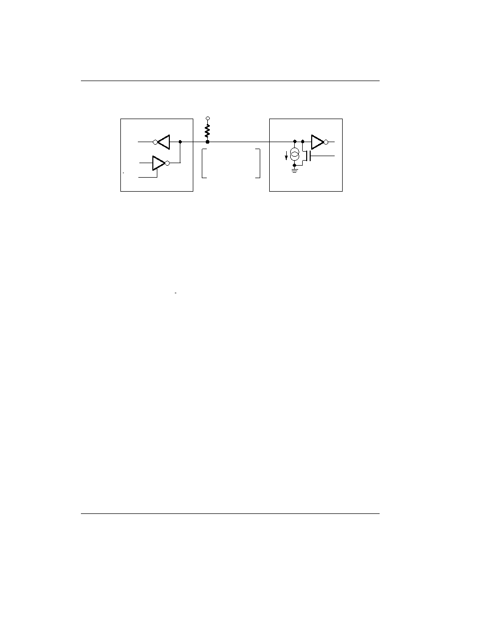
HARDWARE CONFIGURATION Figure 8
VPUP
DS242X 1–WIRE PORT
RX
TX
100 OHM
MOSFET
5 k
TYP.
RX
TX
RX = RECEIVE
TX = TRANSMIT
5
A
TYP.
BUS MASTER
DATA
OPEN DRAIN
PORT PIN
1–WIRE BUS SYSTEM
The 1–Wire bus is a system which has a single bus mas-
ter and one or more slaves. In all instances the DS242X
is a slave device. The bus master is typically a micro-
controller. The discussion of this bus system is broken
down into three topics: hardware configuration, transac-
tion sequence, and 1–Wire signaling (signal types and
timing). A 1–Wire protocol defines bus transactions in
terms of the bus state during specific time slots that are
initiated on the falling edge of sync pulses from the bus
master. For a more detailed protocol description, refer
to Chapter 4 of the Book of DS19xx iButton Standards.
HARDWARE CONFIGURATION
The 1–Wire bus has only a single line by definition; it is
important that each device on the bus be able to drive it
at the appropriate time. To facilitate this, each device
attached to the 1–Wire bus must have open drain or
3–state outputs. The 1–Wire port of the DS242X is open
drain with an internal circuit equivalent to that shown in
Figure 8. A multidrop bus consists of a 1–Wire bus with
multiple slaves attached. At regular speed the 1–Wire
bus has a maximum data rate of 16.3k bits per second.
The speed can be boosted to 142k bits per second by
activating the Overdrive Mode.
The 1–Wire bus
requires a pull–up resistor of approximately 5 k
.
The idle state for the 1–Wire bus is high. If for any rea-
son a transaction needs to be suspended, the bus
MUST be left in the idle state if the transaction is to
resume. If this does not occur and the bus is left low for
more than 16
s (Overdrive Speed) or more than 120 s
(regular speed), one or more devices on the bus may be
reset.
TRANSACTION SEQUENCE
The protocol for accessing the DS242X via the 1–Wire
port is as follows:
Initialization
ROM Function Command
Memory Function Command
Transaction/Data
INITIALIZATION
All transactions on the 1–Wire bus begin with an initial-
ization sequence. The initialization sequence consists
of a reset pulse transmitted by the bus master followed
by presence pulse(s) transmitted by the slave(s).
The presence pulse lets the bus master know that the
DS242X is on the bus and is ready to operate. For more
details, see the “1–Wire Signaling” section.
ROM FUNCTION COMMANDS
Once the bus master has detected a presence, it can
issue one of the six ROM function commands. All ROM
function commands are eight bits long. A list of these
commands follows (refer to flowchart in Figure 9):
Read ROM [33H]
This command allows the bus master to read the
DS242X’s 8–bit family code, unique 48–bit serial num-
ber, and 8–bit CRC. This command can only be used if
there is a single DS242X on the bus. If more than one
slave is present on the bus, a data collision will occur
when all slaves try to transmit at the same time (open
drain will produce a wired–AND result). The resultant
family code and 48–bit serial number will result in a mis-
match of the CRC.
相关PDF资料 |
PDF描述 |
|---|---|
| DS2423P/T&R | SPECIALTY MEMORY CIRCUIT, PDSO6 |
| DS2423P | SPECIALTY MEMORY CIRCUIT, PDSO6 |
| DS2423X | SPECIALTY MEMORY CIRCUIT, UUC |
| DS2423 | 4K X 1 STANDARD SRAM, PDSO6 |
| DS2422 | 1K X 1 STANDARD SRAM, PDSO6 |
相关代理商/技术参数 |
参数描述 |
|---|---|
| DS2423 | 制造商:DALLAS 制造商全称:Dallas Semiconductor 功能描述:4kbit 1-Wire RAM with Counter |
| DS2423D/T&R | 制造商:Maxim Integrated Products 功能描述:IC SRAM 4KBIT 6FLIPCHIP |
| DS2423D/T&R | 功能描述:IC SRAM 4KBIT 6FCHIP RoHS:否 类别:集成电路 (IC) >> 存储器 系列:- 标准包装:150 系列:- 格式 - 存储器:EEPROMs - 串行 存储器类型:EEPROM 存储容量:4K (2 x 256 x 8) 速度:400kHz 接口:I²C,2 线串口 电源电压:2.5 V ~ 5.5 V 工作温度:-40°C ~ 85°C 封装/外壳:8-VFDFN 裸露焊盘 供应商设备封装:8-DFN(2x3) 包装:管件 产品目录页面:1445 (CN2011-ZH PDF) |
| DS2423MRAB0 | 制造商:Thomas & Betts 功能描述:300A,NLT,3P4W,MG,423,3P480V |
| DS2423P | 功能描述:静态随机存取存储器 RoHS:否 制造商:Cypress Semiconductor 存储容量:16 Mbit 组织:1 M x 16 访问时间:55 ns 电源电压-最大:3.6 V 电源电压-最小:2.2 V 最大工作电流:22 uA 最大工作温度:+ 85 C 最小工作温度:- 40 C 安装风格:SMD/SMT 封装 / 箱体:TSOP-48 封装:Tray |
发布紧急采购,3分钟左右您将得到回复。