- 您现在的位置:买卖IC网 > PDF目录17075 > EVAL-AD5064-1EBZ (Analog Devices Inc)BOARD EVALUATION FOR AD5064-1 PDF资料下载
参数资料
| 型号: | EVAL-AD5064-1EBZ |
| 厂商: | Analog Devices Inc |
| 文件页数: | 14/28页 |
| 文件大小: | 0K |
| 描述: | BOARD EVALUATION FOR AD5064-1 |
| 产品培训模块: | DAC Architectures |
| 标准包装: | 1 |
| 系列: | nanoDAC™ |
| DAC 的数量: | 4 |
| 位数: | 16 |
| 采样率(每秒): | 125k |
| 数据接口: | 串行 |
| 设置时间: | 8µs |
| DAC 型: | 电压 |
| 工作温度: | -40°C ~ 125°C |
| 已供物品: | 板 |
| 已用 IC / 零件: | AD5064 |
第1页第2页第3页第4页第5页第6页第7页第8页第9页第10页第11页第12页第13页当前第14页第15页第16页第17页第18页第19页第20页第21页第22页第23页第24页第25页第26页第27页第28页
Data Sheet
AD5024/AD5044/AD5064
Rev. F | Page 21 of 28
MODES OF OPERATION
There are three main modes of operation: standalone mode
where a single device is used, daisy-chain mode for a system
that contains several DACs, and power-down mode when the
supply current falls to 0.4 A at 5 V.
Standalone Mode
The write sequence begins by bringing the SYNC line low. Data
from the DIN line is clocked into the 32-bit shift register on the
falling edge of SCLK. The serial clock frequency can be as high
as 50 MHz, making the AD5024/AD5044/AD5064/AD5064-1
compatible with high speed DSPs. On the 32nd falling clock edge,
the last data bit is clocked in and the programmed function is
executed, that is, an LDAC-dependent change in DAC register
contents and/or a change in the mode of operation. At this
stage, the SYNC line can be kept low or be brought high. In
either case, it must be brought high for a minimum of 3 s
sequence so that a falling edge of SYNC can initiate the next
write sequence. SYNC should be idled at rails between write
sequences for even lower power operation of the part.
SYNC Interrupt
In a normal write sequence, the SYNC line is kept low for at
least 32 falling edges of SCLK, and the DAC is updated on the
32nd falling edge. However, if SYNC is brought high before the
32nd falling edge, this acts as an interrupt to the write sequence.
The write sequence is seen as invalid. Neither an update of the
DAC register contents nor a change in the operating mode
occurs (see Figure 50).
Daisy-Chaining
For systems that contain several DACs the SDO pin can be
used to daisy-chain several devices together and provide serial
readback.
The daisy-chain mode is enabled through a software executable
daisy-chain enable (DCEN) command. Command 1000 is
reserved for this DCEN function (see Table 8). The daisy-chain
mode is enabled by setting Bit DB1 in the DCEN register. The
default setting is standalone mode, where DB1 = 0.
Table 10 shows how the state of the bit corresponds to the mode
of operation of the device.
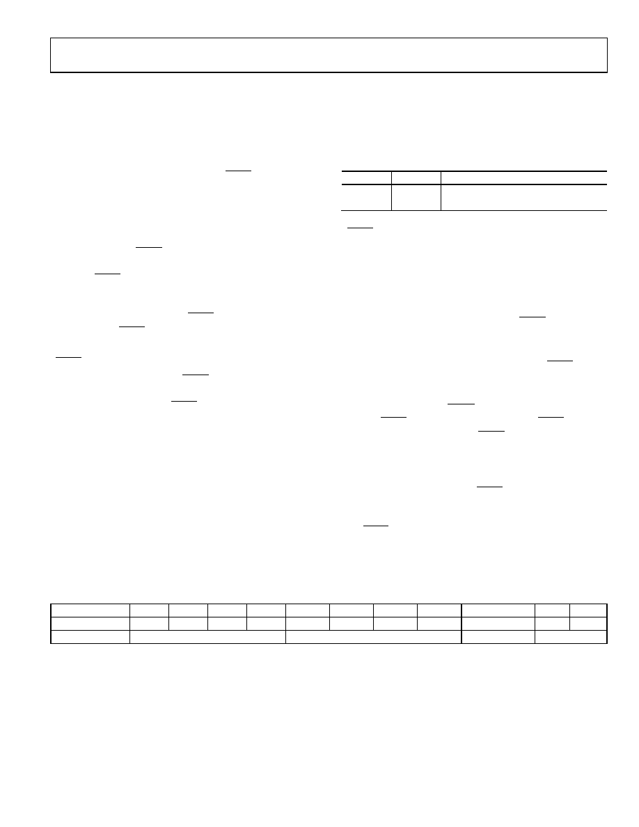
Table 10. DCEN (Daisy-Chain Enable) Register
DB1
DB0
Description
0
X
Standalone mode (default)
1
X
DCEN mode
The SCLK is continuously applied to the shift register when
SYNC is low. If more than 32 clock pulses are applied, the data
ripples out of the shift register and appears on the SDO line.
This data is clocked out on the rising edge of SCLK and is valid
on the falling edge. By connecting this line to the DIN input on
the next DAC in the chain, a daisy-chain interface is constructed.
Each DAC in the system requires 32 clock pulses; therefore, the
total number of clock cycles must equal 32N, where N is the
total number of devices that are updated. If SYNC is taken high
at a clock that is not a multiple of 32, it is considered an invalid
frame and the data is discarded.
When the serial transfer to all devices is complete, SYNC is
taken high. This prevents any further data from being clocked
into the shift register.
In daisy-chain mode, the LDAC pin cannot be tied permanently
low. The LDAC pin must be used in asynchronous LDAC update
mode, as shown in Figure 5. The LDAC pin must be brought
high after pulsing. This allows all DAC outputs to simulta-
neously update.
The serial clock can be continuous or a gated clock. A continuous
SCLK source can be used only if SYNC can be held low for the
correct number of clock cycles. In gated clock mode, a burst
clock containing the exact number of clock cycles must be used,
and SYNC must be taken high after the final clock to latch the data.
Table 11. 32-Bit Shift Register Contents for Daisy-Chain Enable
MSB
LSB
DB31 to DB28
DB27
DB26
DB25
DB24
DB23
DB22
DB21
DB20
DB19 to DB2
DB1
DB0
X
1
0
X
1/0
X
Don’t cares
Command bits (C3 to C0)
Address bits (A3 to A0)
Don’t cares
DCEN register
相关PDF资料 |
PDF描述 |
|---|---|
| 0210490846 | CABLE JUMPER 1.25MM .203M 15POS |
| AP2152ASG-13 | IC PWR SW USB 2CH 0.5A 8-SOIC |
| EVAL-AD5360EBZ | BOARD EVAL FOR AD5360 |
| V375C2E50B | CONVERTER MOD DC/DC 2V 50W |
| EVAL-AD5391EBZ | BOARD EVALUATION FOR AD5391 |
相关代理商/技术参数 |
参数描述 |
|---|---|
| EVAL-AD5064EBZ | 功能描述:BOARD EVAL FOR AD5064 RoHS:是 类别:编程器,开发系统 >> 评估板 - 数模转换器 (DAC) 系列:nanoDAC™ 产品培训模块:Lead (SnPb) Finish for COTS Obsolescence Mitigation Program 标准包装:1 系列:- DAC 的数量:4 位数:12 采样率(每秒):- 数据接口:串行,SPI? 设置时间:3µs DAC 型:电流/电压 工作温度:-40°C ~ 85°C 已供物品:板 已用 IC / 零件:MAX5581 |
| EVAL-AD5065EBZ | 制造商:AD 制造商全称:Analog Devices 功能描述:Fully Accurate 12-/14-/16-Bit VOUT DAC SPI Interface 2.7 V to 5.5 V in a TSSOP |
| EVAL-AD5066EBZ | 制造商:AD 制造商全称:Analog Devices 功能描述:Fully Accurate 16-Bit UnBuffered VOUT DAC SPI Interface 2.7 V to 5.5 V in a TSSOP |
| EVAL-AD5100EBZ | 功能描述:BOARD EVAL FOR AD5100 RoHS:是 类别:编程器,开发系统 >> 评估演示板和套件 系列:- 标准包装:1 系列:- 主要目的:电信,线路接口单元(LIU) 嵌入式:- 已用 IC / 零件:IDT82V2081 主要属性:T1/J1/E1 LIU 次要属性:- 已供物品:板,电源,线缆,CD 其它名称:82EBV2081 |
| EVAL-AD5110SDZ | 功能描述:BOARD EVAL FOR AD5110 RoHS:是 类别:编程器,开发系统 >> 评估演示板和套件 系列:- 标准包装:1 系列:- 主要目的:电信,线路接口单元(LIU) 嵌入式:- 已用 IC / 零件:IDT82V2081 主要属性:T1/J1/E1 LIU 次要属性:- 已供物品:板,电源,线缆,CD 其它名称:82EBV2081 |
发布紧急采购,3分钟左右您将得到回复。