- 您现在的位置:买卖IC网 > PDF目录17075 > EVAL-AD5064-1EBZ (Analog Devices Inc)BOARD EVALUATION FOR AD5064-1 PDF资料下载
参数资料
| 型号: | EVAL-AD5064-1EBZ |
| 厂商: | Analog Devices Inc |
| 文件页数: | 16/28页 |
| 文件大小: | 0K |
| 描述: | BOARD EVALUATION FOR AD5064-1 |
| 产品培训模块: | DAC Architectures |
| 标准包装: | 1 |
| 系列: | nanoDAC™ |
| DAC 的数量: | 4 |
| 位数: | 16 |
| 采样率(每秒): | 125k |
| 数据接口: | 串行 |
| 设置时间: | 8µs |
| DAC 型: | 电压 |
| 工作温度: | -40°C ~ 125°C |
| 已供物品: | 板 |
| 已用 IC / 零件: | AD5064 |
第1页第2页第3页第4页第5页第6页第7页第8页第9页第10页第11页第12页第13页第14页第15页当前第16页第17页第18页第19页第20页第21页第22页第23页第24页第25页第26页第27页第28页
Data Sheet
AD5024/AD5044/AD5064
Rev. F | Page 23 of 28
CLEAR CODE REGISTER
The AD5024/AD5044/AD5064/AD5064-1 have a hardware
CLR pin that is an asynchronous clear input. The CLR input is
falling edge sensitive. Bringing the CLR line low clears the
contents of the input register and the DAC registers to the data
contained in the user-configurable CLR register and sets the
analog outputs accordingly (see Table 14). This function can be
used in system calibration or reset to load zero scale, midscale,
or full scale to all channels together. Note that zero scale and full
scale are outside the linear region of the DAC. These clear code
values are user-programmable by setting two bits, Bit DB1 and
Bit DB0, in the shift register (see Table 14). The default setting
clears the outputs to 0 V. Command 0101 is designated for
loading the clear code register (see Table 8).
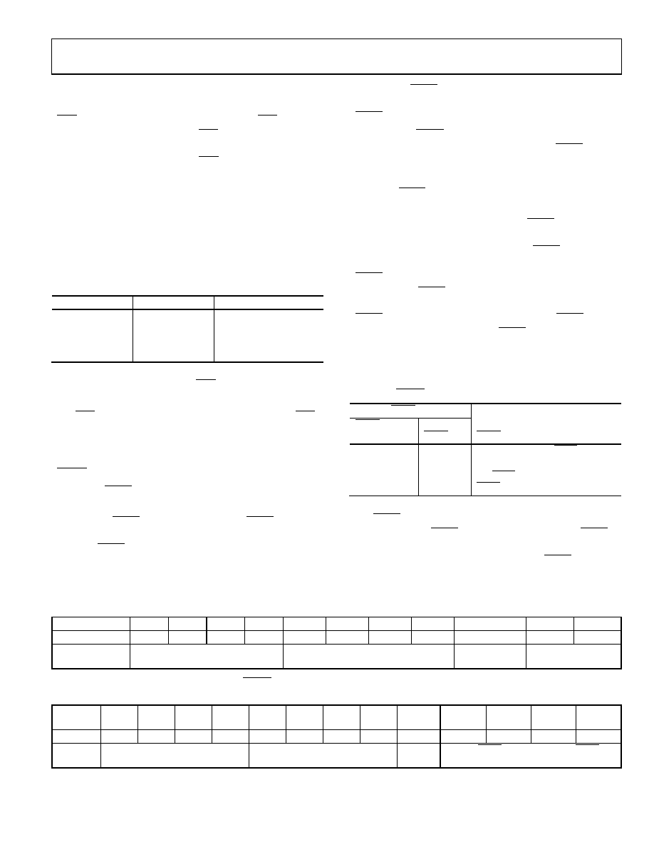
Table 14. Clear Code Register
DB1 (CR1)
DB0 (CR0)
Clears to Code
0
0x0000
0
1
0x8000
1
0
0xFFFF
1
No operation
The part exits clear code mode on the 32nd falling edge of the
next write to the part. If hardware CLR pin is activated during a
write sequence, the write is aborted.
The CLR pulse activation time, which is the falling edge of CLR
to when the output starts to change, is typically 10.6 μs. See
Table 16 for contents of the shift register while loading the clear
code register.
LDAC FUNCTION
Hardware LDAC Pin
The outputs of all DACs can be updated simultaneously using
the hardware LDAC pin, as shown in Figure 4. LDAC can be
permanently low or pulsed. There are two methods of using the
hardware LDAC pin, synchronously and asynchronously.
Synchronous LDAC: After new data is read, the DAC registers
are updated on the falling edge of the 32nd SCLK pulse, provided
LDAC is held low.
Asynchronous LDAC: The outputs are not updated at the same
time that the input registers are written to. When LDAC is
pulsed low, the DAC registers are updated with the contents of
the input registers.
Software LDAC Function
Alternatively, the outputs of all DACs can be updated simulta-
neously or individually using the software LDAC function by
writing to Input Register n and updating all DAC registers.
Command 0010 is reserved for this software LDAC function.
Writing to the DAC using Command 0110 loads the 4-bit
LDAC register (DB3 to DB0). The default for each channel
is 0; that is, the LDAC pin works normally. Setting the bits to 1
updates the DAC channel regardless of the state of the hardware
LDAC pin, so that it effectively sees the hardware LDAC pin as
being tied low (see Table 15 for the LDAC register mode of
operation.) This flexibility is useful in applications where the
user wants to simultaneously update select channels while the
remainder of the channels are synchronously updating.
Table 15. LDAC Overwrite Definition
Load LDAC Register
LDAC Bits
(DB3 to DB0)
LDAC Pin
LDAC Operation
0
1 or 0
Determined by the LDAC pin.
1
DAC channels update, overrides
the LDAC pin. DAC channels see
LDAC as 0.
1
X = don’t care.
The LDAC register gives the user extra flexibility and control
over the hardware LDAC pin (see Table 17). Setting the LDAC
bits (DB0 to DB3) to 0 for a DAC channel means that this
channel’s update is controlled by the hardware LDAC pin.
Table 16. 32-Bit Shift Register Contents for Clear Code Function
MSB
LSB
DB31 to DB28
DB27
DB26
DB25
DB24
DB23
DB22
DB21
DB20
DB19 to DB2
DB1
DB0
X
0
1
0
1
X
1/0
Don’t cares
Command bits (C3 to C0)
Address bits (A3 to A0)
Don’t cares
Clear code register
(CR1 to CR0)
Table 17. 32-Bit Shift Register Contents for LDAC Overwrite Function
MSB
LSB
DB31 to
DB28
DB27
DB26
DB25
DB24
DB23
DB22
DB21
DB20
DB19
to DB4
DB3
DB2
DB1
DB0
X
0
1
0
X
DAC D
DAC C
DAC B
DAC A
Don’t
cares
Command bits (C3 to C0)
Address bits (A3 to A0)—
don’t cares
Don’t
cares
Setting LDAC bits to 1 overrides LDAC pin
相关PDF资料 |
PDF描述 |
|---|---|
| 0210490846 | CABLE JUMPER 1.25MM .203M 15POS |
| AP2152ASG-13 | IC PWR SW USB 2CH 0.5A 8-SOIC |
| EVAL-AD5360EBZ | BOARD EVAL FOR AD5360 |
| V375C2E50B | CONVERTER MOD DC/DC 2V 50W |
| EVAL-AD5391EBZ | BOARD EVALUATION FOR AD5391 |
相关代理商/技术参数 |
参数描述 |
|---|---|
| EVAL-AD5064EBZ | 功能描述:BOARD EVAL FOR AD5064 RoHS:是 类别:编程器,开发系统 >> 评估板 - 数模转换器 (DAC) 系列:nanoDAC™ 产品培训模块:Lead (SnPb) Finish for COTS Obsolescence Mitigation Program 标准包装:1 系列:- DAC 的数量:4 位数:12 采样率(每秒):- 数据接口:串行,SPI? 设置时间:3µs DAC 型:电流/电压 工作温度:-40°C ~ 85°C 已供物品:板 已用 IC / 零件:MAX5581 |
| EVAL-AD5065EBZ | 制造商:AD 制造商全称:Analog Devices 功能描述:Fully Accurate 12-/14-/16-Bit VOUT DAC SPI Interface 2.7 V to 5.5 V in a TSSOP |
| EVAL-AD5066EBZ | 制造商:AD 制造商全称:Analog Devices 功能描述:Fully Accurate 16-Bit UnBuffered VOUT DAC SPI Interface 2.7 V to 5.5 V in a TSSOP |
| EVAL-AD5100EBZ | 功能描述:BOARD EVAL FOR AD5100 RoHS:是 类别:编程器,开发系统 >> 评估演示板和套件 系列:- 标准包装:1 系列:- 主要目的:电信,线路接口单元(LIU) 嵌入式:- 已用 IC / 零件:IDT82V2081 主要属性:T1/J1/E1 LIU 次要属性:- 已供物品:板,电源,线缆,CD 其它名称:82EBV2081 |
| EVAL-AD5110SDZ | 功能描述:BOARD EVAL FOR AD5110 RoHS:是 类别:编程器,开发系统 >> 评估演示板和套件 系列:- 标准包装:1 系列:- 主要目的:电信,线路接口单元(LIU) 嵌入式:- 已用 IC / 零件:IDT82V2081 主要属性:T1/J1/E1 LIU 次要属性:- 已供物品:板,电源,线缆,CD 其它名称:82EBV2081 |
发布紧急采购,3分钟左右您将得到回复。