- 您现在的位置:买卖IC网 > PDF目录97935 > EVB3020A GSM Multiband RF Transceiver PDF资料下载
参数资料
| 型号: | EVB3020A |
| 英文描述: | GSM Multiband RF Transceiver |
| 中文描述: | 手机多频段射频收发器 |
| 文件页数: | 15/44页 |
| 文件大小: | 409K |
| 代理商: | EVB3020A |
第1页第2页第3页第4页第5页第6页第7页第8页第9页第10页第11页第12页第13页第14页当前第15页第16页第17页第18页第19页第20页第21页第22页第23页第24页第25页第26页第27页第28页第29页第30页第31页第32页第33页第34页第35页第36页第37页第38页第39页第40页第41页第42页第43页第44页

Advance Data Sheet
W3020 GSM Multiband RF Transceiver
December 1999
22
Lucent Technologies Inc.
Programming Information (continued)
TR Register (continued)
B: Band Select
When set low, the GSM900 transceiver circuits are
enabled and the GSM1800 transceiver circuits are
disabled. When set high, the GSM1800 transceiver
circuits are enabled and the GSM900 transceiver
circuits are disabled. The transceiver circuits that
change with the setting of the band bit B are the LNA,
the RF mixer, the receive UHF LO1 buffer, the
transmit UHF LO1 buffer, and the LO2 divider for the
modulator IF LO phase shifter circuit. The normal LO2
division factor for GSM900 is divide-by-2; for
GSM1800, the normal LO2 division factor is divide-by-
3. Note that bits T2 and T1 also affect the transmitter
LO2 division factor when set high (see Table 23 and
Table 24).
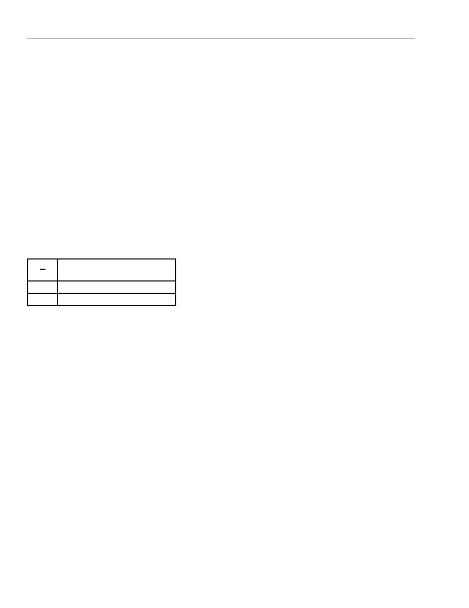
Table 14. B: Band Select
B
Bit 23
Function
0
GSM900 Path On
1
GSM1800/1900 Path On
Note: When programmed via the same three-wire bus as
the W3000, updating this bit in W3020 also
updates it in W3000, and vice versa.
MO[3:1]: Mode Control
The various system modes of the W3020 are set by
the mode control bits. These are active in both the TR
and MAIN registers. The W3000 will also power up
with the W3020 in any of the valid modes set by the
mode bits in the TR or MAIN registers. The mode bit
settings for each W3020 system mode are given in
Table 15. The corresponding typical supply current for
the IC in each mode is shown in the Supply Currents
table on page 9.
In sleep mode, both the W3020 and W3000 are
powered down, and the supply current is in the A
range. The transmit PLL settling mode is used prior to
a transmit burst in order to power up and lock the LO1
and LO2 VCO/PLL synthesizers and the respective
RF and IF LO buffers connecting to the modulator
circuit. The LO2 divide-by circuits remain off during
this mode. Similarly, the receive PLL settling mode is
used prior to the receive dc calibration time slot and
subsequent receive burst in order to power up and
lock the LO1 and LO2 VCO/PLL synthesizers and the
respective RF and IF LO buffers connecting to the RF
mixer and IF strip. The RF mixer can be turned on in
this mode by setting the C9 (RF mixer on during
settling) bit high in the CONFIG register (see Table
30). The transmitter ON mode turns on all the same
circuits as the transmit PLL settling mode along with
the I/Q modulator and up-conversion mixer.
The receiver ON mode turns on all the same circuits
as the receive PLL settling mode along, with the LNA
(if enabled by the G0 bit—see Table 26), RF mixer,
and IF amplifiers and demodulator. When first going
into receive mode, a baseband LP filter tune is
performed, if requested, by setting the FTR (filter tune
request) bit high in the TR register and the C6 (filter
tune disable) bit low in the CONFIG register (see
Table 20 and Table 35, respectively, and the Low-
Pass Filter Tuning section). Next, a dc offset
calibration cycle is performed if the DS (dc correction
skip) bit is low in the TR register and the C5 (dc
correction disable) bit is low in the CONFIG register
(see Table 22 and Table 36, respectively). The default
condition is that the LNA turns off during the dc
calibration if the C2 (LNA mode during dc calibration)
bit is low in the CONFIG register (see Table 37). The
other default condition is that the RF mixer LO1 buffer
turns off during the dc calibration if the C3 (RX LO1
buffer mode during dc calibration) bit is low in the
CONFIG register (see Table 38).
During this event, the transmit LO1 buffer will turn on
to act as a load stage for the UHF LO1 buffer. (For
additional information on the dc offset calibration, see
the dc Offset Correction Timing section.) After the dc
calibration cycle, all the receive circuits turn on as
mentioned above for the receive burst.
相关PDF资料 |
PDF描述 |
|---|---|
| EVB3020A-IFBD | GSM Multiband RF Transceiver |
| EVB3030A | W3030 3 V Dual-Mode IF Cellular Receiver |
| EVB72001 | EVB72001 EValuation board for TH72001 |
| EVB72002 | EVB72002 EValuation Board for TH72002 |
| EVB72011 | EVB72011 EValuation Board for TH72011 |
相关代理商/技术参数 |
参数描述 |
|---|---|
| EVB3020A-IFBD | 制造商:AGERE 制造商全称:AGERE 功能描述:GSM Multiband RF Transceiver |
| EVB3030A | 制造商:AGERE 制造商全称:AGERE 功能描述:W3030 3 V Dual-Mode IF Cellular Receiver |
| EVB-3250 | 功能描述:界面开发工具 Evaluation Board RoHS:否 制造商:Bourns 产品:Evaluation Boards 类型:RS-485 工具用于评估:ADM3485E 接口类型:RS-485 工作电源电压:3.3 V |
| EVB32-M8L | 制造商:Leviton Manufacturing Co 功能描述: |
| EVB-3300 | 功能描述:界面开发工具 USB3300 Hi-Speed USB Phy Evaluation Board RoHS:否 制造商:Bourns 产品:Evaluation Boards 类型:RS-485 工具用于评估:ADM3485E 接口类型:RS-485 工作电源电压:3.3 V |
发布紧急采购,3分钟左右您将得到回复。