- 您现在的位置:买卖IC网 > PDF目录1920 > FMS6502MTC24 (Fairchild Semiconductor)IC VIDEO SWITCH 8IN/6OUT 24TSSOP PDF资料下载
参数资料
| 型号: | FMS6502MTC24 |
| 厂商: | Fairchild Semiconductor |
| 文件页数: | 2/13页 |
| 文件大小: | 0K |
| 描述: | IC VIDEO SWITCH 8IN/6OUT 24TSSOP |
| 标准包装: | 61 |
| 功能: | 视频交叉点开关 |
| 电路: | 1 x 8:6 |
| 电压电源: | 单电源 |
| 电压 - 电源,单路/双路(±): | 3.135 V ~ 5.25 V |
| 电流 - 电源: | 55mA |
| 工作温度: | -40°C ~ 85°C |
| 安装类型: | 表面贴装 |
| 封装/外壳: | 24-TSSOP(0.173",4.40mm 宽) |
| 供应商设备封装: | 24-TSSOP |
| 包装: | 管件 |
FMS6502
8-Input,
6-Output
V
ideo
Switch
Matrix
with
Output
Drivers,
Input
Cl
amp,
and
Bias
Circuitry
2006 Fairchild Semiconductor Corporation
www.fairchildsemi.com
FMS6502 Rev. 1.0.0
10
Crosstalk
Crosstalk is an important consideration when using the
FMS6502. Input and output crosstalk represent the two
major coupling modes that may be present in a typical
application. Input crosstalk is crosstalk in the input pins
and switches when the interfering signal drives an open
switch. It is dominated by inductive coupling in the pack-
age lead frame between adjacent leads. It decreases
rapidly as the interfering signal moves further away from
the pin adjacent to the input signal selected. Output
crosstalk is coupling from one driven output to another
active output. It decreases with increasing load imped-
ance as it is caused mainly by ground and power cou-
pling between output amplifiers. If a signal is driving an
open switch, its crosstalk is mainly input crosstalk. If it is
driving a load through an active output, its crosstalk is
mainly output crosstalk.
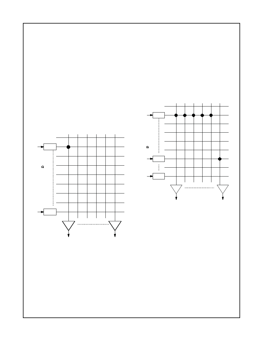
Input and output crosstalk measurements are performed
with the test configuration shown in Figure 13.
Figure 13. Test Configuration for Crosstalk
For input crosstalk, the switch is open and all inputs are
in bias mode. Channel 1 input is driven with a 1Vpp sig-
nal, while all other inputs are AC terminated with 75
Ω. All
outputs are enabled and crosstalk is measured from IN1
to any output.
For output crosstalk, the switch is closed. Crosstalk from
OUT1 to any output is measured.
Crosstalk from multiple sources into a given channel is
measured with the setup shown in Figure 14. Input In1 is
driven with a 1Vpp pulse source and connected to out-
puts Out1 to Out8. Input In9 is driven with a secondary,
asynchronous gray field video signal and is connected to
Out9. All other inputs are AC terminated with 75
Ω.
Crosstalk effects on the gray field are measured and cal-
culated with respect to a standard 1Vpp output measured
at the load.
If not all inputs and outputs are needed, avoid using
adjacent channels to reduce crosstalk.
Figure 14. Test Configuration for Multi-Channel
Crosstalk
Bias
IN1
OUT1
Bias
IN8
OUT6
Gain = 6dB
Out1 = 2.0VPP
Input Crosstalk from IN1
to OUTx
Output Crosstalk from
OUT1 to OUTx
TERMINATION
IN2 - IN8 are
AC-Term to
Ground
w/75
IN1 = 1VPP
Open switch
for input
crosstalk.
Close switch
for output
crosstalk.
Bias
IN1
OUT1
Bias
IN8
OUT6
TERMINATION
Bias
IN6
IN1 driven with
SD video 1V
PP.
IN6 driven with
asynchronous
SD video 1V
PP.
IN2,3,4,5,7,8 are
AC-term to GND
with 75 .
Measure crosstalk from
channels 1-5 into
channel6
相关PDF资料 |
PDF描述 |
|---|---|
| FSA110UMX_F113 | IC SWITCH DPST 10-UMLP |
| FSA1208BQX | IC SWITCH OCTAL SPST 20DQFN |
| FSA1211UMX | IC SWITCH SPST 28UMLP |
| FSA1256AL8X | IC SWITCH DUAL SPST 8MICROPAK |
| FSA2000UMX | IC HS-USB/AUDIO SWITCH 16UMLP |
相关代理商/技术参数 |
参数描述 |
|---|---|
| FMS6502MTC24X | 功能描述:视频 IC Switch Video 8I 6O Matrix-Output Dvrs RoHS:否 制造商:Fairchild Semiconductor 工作电源电压:5 V 电源电流:80 mA 最大工作温度:+ 85 C 封装 / 箱体:TSSOP-28 封装:Reel |
| FMS6601_AAA3026B WAF | 制造商:Fairchild Semiconductor Corporation 功能描述: |
| FMS6646 | 制造商:FAIRCHILD 制造商全称:Fairchild Semiconductor 功能描述:Six Channel, SD/HD (1080p) Video Filter Driver |
| FMS6646_09 | 制造商:FAIRCHILD 制造商全称:Fairchild Semiconductor 功能描述:Six Channel, SD/HD 1080p Video Filter Driver |
| FMS6646MTC20X | 功能描述:视频 IC Six Chan SD/Full HD Video Filter Driver RoHS:否 制造商:Fairchild Semiconductor 工作电源电压:5 V 电源电流:80 mA 最大工作温度:+ 85 C 封装 / 箱体:TSSOP-28 封装:Reel |
发布紧急采购,3分钟左右您将得到回复。