- 您现在的位置:买卖IC网 > PDF目录16742 > FSLBOT (Freescale Semiconductor)KIT TOWER MECH BOARD PDF资料下载
参数资料
| 型号: | FSLBOT |
| 厂商: | Freescale Semiconductor |
| 文件页数: | 25/46页 |
| 文件大小: | 0K |
| 描述: | KIT TOWER MECH BOARD |
| 视频文件: | Freescale Tower Overview - Another Geek Moment Freescale Tower Labs 1 & 2 - Another Geek Moment |
| 特色产品: | Tower Mechatronics Board and Robot |
| 标准包装: | 1 |
| 系列: | ColdFire® |
| 主要目的: | 机器人 |
| 嵌入式: | 否 |
| 主要属性: | 步行机器人结构 |
| 已供物品: | 线路板,4 PWM 伺服系统,用户指南,汇编指令 |
第1页第2页第3页第4页第5页第6页第7页第8页第9页第10页第11页第12页第13页第14页第15页第16页第17页第18页第19页第20页第21页第22页第23页第24页当前第25页第26页第27页第28页第29页第30页第31页第32页第33页第34页第35页第36页第37页第38页第39页第40页第41页第42页第43页第44页第45页第46页
MCF52259 ColdFire Microcontroller, Rev. 5
Electrical Characteristics
Freescale
31
2.8
Clock Source Electrical Specifications
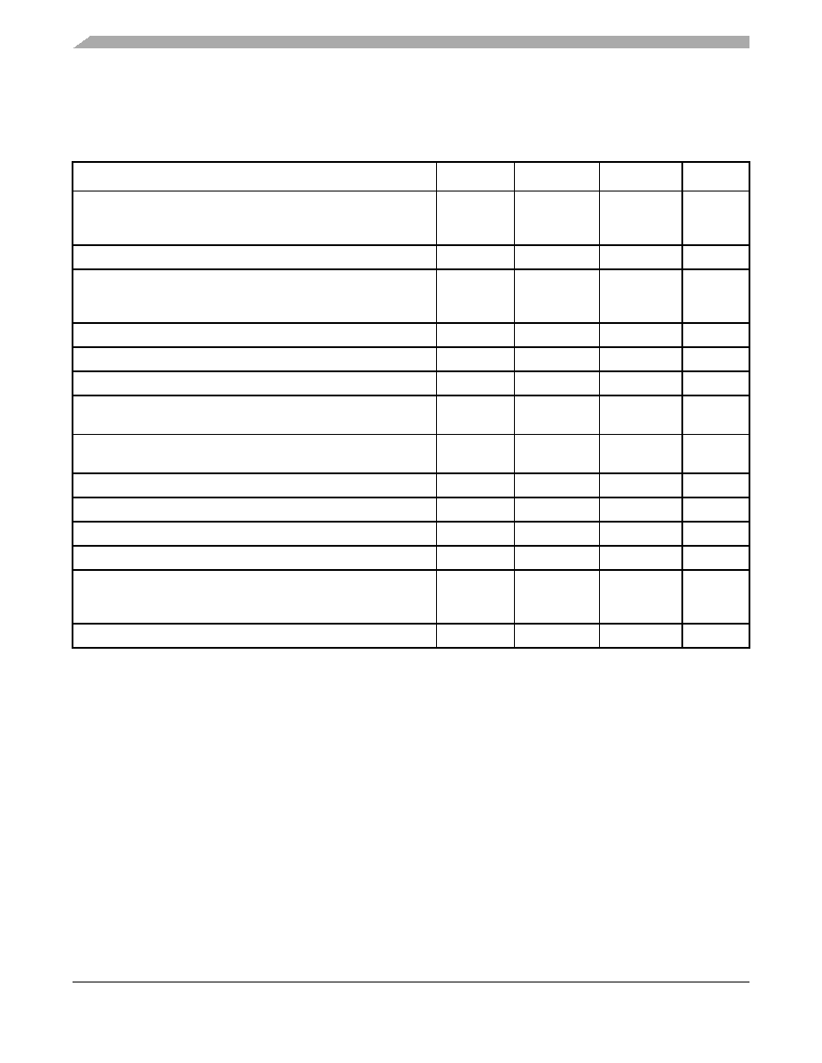
Table 14. Oscillator and PLL Specifications
(VDD and VDDPLL = 3.0 to 3.6 V, VSS = VSSPLL = 0 V)
Characteristic
Symbol
Min
Max
Unit
Clock Source Frequency Range of EXTAL Frequency Range
Crystal
External1
1 In external clock mode, it is possible to run the chip directly from an external clock source without enabling the PLL.
fcrystal
fext
12
0
25.02
66.67 or 80
2 This value has been updated.
MHz
PLL reference frequency range
fref_pll
210.0
MHz
System frequency 3
External clock mode
On-chip PLL frequency
3 All internal registers retain data at 0 Hz.
fsys
0
fref / 32
66.67 or 804
4 Depending on packaging; see the orderable part number summary (Table 2).
MHz
Loss of reference frequency 5, 7
5 Loss of Reference Frequency is the reference frequency detected internally, which transitions the PLL into self clocked mode.
fLOR
100
1000
kHz
Self clocked mode frequency 6
6 Self clocked mode frequency is the frequency at which the PLL operates when the reference frequency falls below f
LOR with
default MFD/RFD settings.
fSCM
15
MHz
Crystal start-up time 7, 8
7 This parameter is characterized before qualification rather than 100% tested.
8 Proper PC board layout procedures must be followed to achieve specifications.
tcst
—0.1
ms
EXTAL input high voltage
External reference
VIHEXT
2.0
3.02
V
EXTAL input low voltage
External reference
VILEXT
VSS
0.8
V
PLL lock time4,9
9 This specification applies to the period required for the PLL to relock after changing the MFD frequency control bits in the
synthesizer control register (SYNCR).
tlpll
—500
s
Duty cycle of reference 4
tdc
40
60
% fref
Frequency un-LOCK range
fUL
–1.5
1.5
% fref
Frequency LOCK range
fLCK
–0.75
0.75
% fref
CLKOUT period jitter 4, 5, 10 ,11, measured at fSYS Max
Peak-to-peak (clock edge to clock edge)
Long term (averaged over 2 ms interval)
10 Jitter is the average deviation from the programmed frequency measured over the specified interval at maximum f
sys.
Measurements are made with the device powered by filtered supplies and clocked by a stable external clock signal. Noise
injected into the PLL circuitry via VDDPLL and VSSPLL and variation in crystal oscillator frequency increase the Cjitter percentage
for a given interval.
11 Based on slow system clock of 40 MHz measured at f
sys max.
Cjitter
—
10
.01
% fsys
On-chip oscillator frequency
foco
7.84
8.16
MHz
相关PDF资料 |
PDF描述 |
|---|---|
| SN65LVDS31-33EVM | EVAL MOD FOR SN65LVDS31/33 |
| 4426R-3 | INDUCTOR AIR CORE 8.0NH SMD |
| RCC10DRYS-S93 | CONN EDGECARD 20POS DIP .100 SLD |
| ADM1169ASTZ-RL7 | IC SEQUENCER/SUPERVISOR 32LQFP |
| 0210490450 | CABLE JUMPER 1.25MM .254M 36POS |
相关代理商/技术参数 |
参数描述 |
|---|---|
| FSLB-S245A | 制造商:HITACHI-METALS 制造商全称:Hitachi Metals, Ltd 功能描述:2012 Size Band Pass Filter for W-LAN/Bluetooth High Attenuation type |
| FSLB-S245C | 制造商:HITACHI-METALS 制造商全称:Hitachi Metals, Ltd 功能描述:2012 Size Chip Multilayer Band Pass Filter |
| FSLBS40 | 制造商:Ferraz Shawmut 功能描述: |
| FSLBS80 | 制造商:FUSES UNLIMITED 功能描述:DISCONNECT SWTCH-600V LOAD BRK?? |
| FSLC-045P | 制造商:HITACHI-METALS 制造商全称:Hitachi Metals, Ltd 功能描述:450 MHz Band Chip Multilayer 90deg. / 3dB Splitter |
发布紧急采购,3分钟左右您将得到回复。