- 您现在的位置:买卖IC网 > PDF目录11800 > FT245RQ-REEL (FTDI, Future Technology Devices International Ltd)IC USB TO PARALLEL FIFO 32-QFN PDF资料下载
参数资料
| 型号: | FT245RQ-REEL |
| 厂商: | FTDI, Future Technology Devices International Ltd |
| 文件页数: | 4/37页 |
| 文件大小: | 0K |
| 描述: | IC USB TO PARALLEL FIFO 32-QFN |
| 产品培训模块: | USB Introduction |
| 标准包装: | 1 |
| 应用: | USB 至 FIFO 控制器 |
| 接口: | USB,FIFO,(同步/异步) |
| 电源电压: | 1.8 V ~ 5.25 V |
| 封装/外壳: | 32-VFQFN 裸露焊盘 |
| 供应商设备封装: | 32-QFN 裸露焊盘(5x5) |
| 包装: | 标准包装 |
| 安装类型: | 表面贴装 |
| 产品目录页面: | 634 (CN2011-ZH PDF) |
| 配用: | 768-1020-ND - MOD USB PARALLEL FIFO DEV FT245R |
| 其它名称: | 768-1012-6 |
第1页第2页第3页当前第4页第5页第6页第7页第8页第9页第10页第11页第12页第13页第14页第15页第16页第17页第18页第19页第20页第21页第22页第23页第24页第25页第26页第27页第28页第29页第30页第31页第32页第33页第34页第35页第36页第37页
Copyright 2010 Future Technology Devices International Limited
12
Document No.: FT_000052
FT245R USB FIFO IC Datasheet Version 2.12
Clearance No.: FTDI# 39
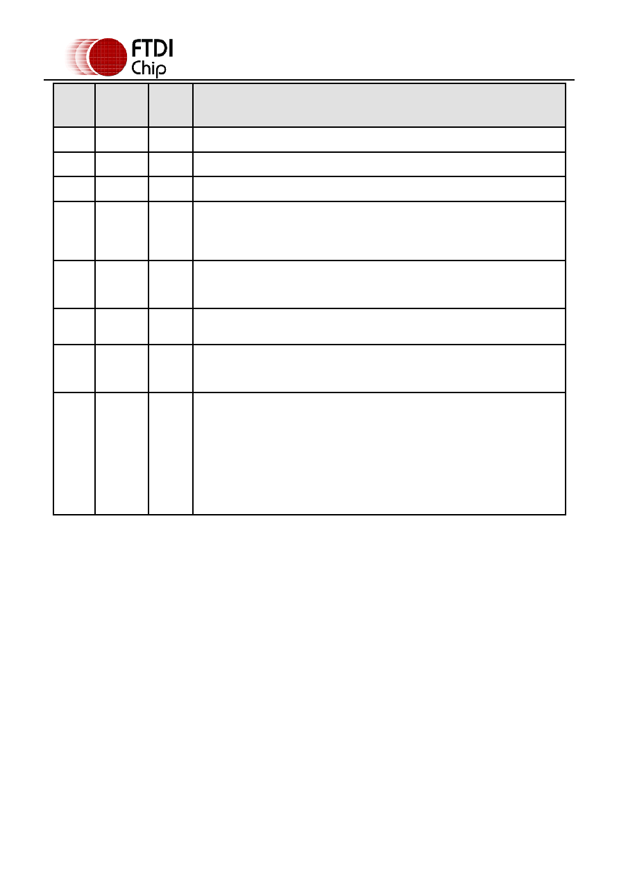
Pin
No.
Name
Type
Description
6
D5
I/O
FIFO Data Bus Bit 5
7
D6
I/O
FIFO Data Bus Bit 6
8
D3
I/O
FIFO Data Bus Bit 3
9
PWREN# Output
Goes low after the device is configured by USB, then high during USB
suspend. Can be used to control power to external logic P-Channel logic
level MOSFET switch. Enable the interface pull-down option when using the
PWREN# pin in this way. Should be pulled to VCCIO with 10kΩ resistors.
10
RD#
Input
Enables the current FIFO data byte from D0…D7 when low. Fetched the next
FIFO data byte (if available) from the receive FIFO buffer when RD# goes
from high to low. See Section 3.5 for timing diagram.
11
WR
Input
Writes the data from byte from D0...D7 pins into the transmit FIFO buffer
when WR goes from high to low. See section 3.6 for timing diagram.
21
TXE#
Output
When high, do not write data into the FIFO. When low, data can be written
into the FIFO by strobing WR high, then low. During reset this signal pin is
tri-state. See Section 3.6 for timing diagram.
22
RXF#
Output
When high, do not read data from the FIFO. When low, there is data
available in the FIFO which can be read by strobing RD# low, then high
again. During reset this signal pin is tri-state. See Section 3.5 for timing
diagram.
If the Remote Wakeup option is enabled in the internal EEPROM, during USB
suspend mode (PWREN# = 1) RXF# becomes an input. This can be used to
wake up the USB host from suspend mode by strobing this pin low for a
minimum of 20ms which will cause the device to request a resume on the
USB bus.
Table 3.8 FIFO Interface Group (see note 3)
Notes:
1. The minimum operating voltage VCC must be +4.0V (could use VBUS=+5V) when
using the internal clock generator. Operation at +3.3V is possible using an external
crystal oscillator.
2. For details on how to use an external crystal, ceramic resonator, or oscillator with the FT245R,
please refer to Section 8.2
3. When used in Input Mode, the input pins are pulled to VCCIO via internal 200kΩ
resistors. These pins can be programmed to gently pull low during USB suspend (
PWREN# = “1”) by setting an option in the internal EEPROM.
相关PDF资料 |
PDF描述 |
|---|---|
| V48A12E500BG2 | CONVERTER MOD DC/DC 12V 500W |
| V48A12E500BF3 | CONVERTER MOD DC/DC 12V 500W |
| V48A12E500BF2 | CONVERTER MOD DC/DC 12V 500W |
| V48A12E500BF | CONVERTER MOD DC/DC 12V 500W |
| V48A12E500BL2 | CONVERTER MOD DC/DC 12V 500W |
相关代理商/技术参数 |
参数描述 |
|---|---|
| FT245RQ-TRAY | 制造商:Future Technology Devices International (FTDI Chip) 功能描述:Single Chip USB Tray |
| FT24B3 031175 | 制造商:Comair Rotron 功能描述:FAN 120X120X25MM 24VDC |
| FT24B3-E2 | 制造商:Comair Rotron 功能描述:FAN FLIGHT II 120X120X25MM 24V |
| FT24B3-E2 | 制造商:Comair Rotron 功能描述:FAN FLIGHT II 120X120X25 24V |
| FT24C02A | 制造商:未知厂家 制造商全称:未知厂家 功能描述:Two-Wire Serial EEPROM |
发布紧急采购,3分钟左右您将得到回复。