- 您现在的位置:买卖IC网 > PDF目录173641 > GS88237BB-V (GSI TECHNOLOGY) 256K x 36 9Mb SCD/DCD Sync Burst SRAM PDF资料下载
参数资料
| 型号: | GS88237BB-V |
| 厂商: | GSI TECHNOLOGY |
| 英文描述: | 256K x 36 9Mb SCD/DCD Sync Burst SRAM |
| 中文描述: | 256K × 36 9Mb以上SCD的/双氰胺同步突发静态存储器 |
| 文件页数: | 9/28页 |
| 文件大小: | 747K |
| 代理商: | GS88237BB-V |
第1页第2页第3页第4页第5页第6页第7页第8页当前第9页第10页第11页第12页第13页第14页第15页第16页第17页第18页第19页第20页第21页第22页第23页第24页第25页第26页第27页第28页
GS88237BB/D-xxxV
Specifications cited are subject to change without notice. For latest documentation see http://www.gsitechnology.com.
Rev: 1.04 6/2006
17/28
2003, GSI Technology
Sleep Mode
During normal operation, ZZ must be pulled low, either by the user or by it’s internal pull down resistor. When ZZ is pulled high,
the SRAM will enter a Power Sleep mode after 2 cycles. At this time, internal state of the SRAM is preserved. When ZZ returns to
low, the SRAM operates normally after ZZ recovery time.
Sleep mode is a low current, power-down mode in which the device is deselected and current is reduced to ISB2. The duration of
Sleep mode is dictated by the length of time the ZZ is in a high state. After entering Sleep mode, all inputs except ZZ become
disabled and all outputs go to High-Z The ZZ pin is an asynchronous, active high input that causes the device to enter Sleep mode.
When the ZZ pin is driven high, ISB2 is guaranteed after the time tZZI is met. Because ZZ is an asynchronous input, pending
operations or operations in progress may not be properly completed if ZZ is asserted. Therefore, Sleep mode must not be initiated
until valid pending operations are completed. Similarly, when exiting Sleep mode during tZZR, only a Deselect or Read commands
may be applied while the SRAM is recovering from Sleep mode.
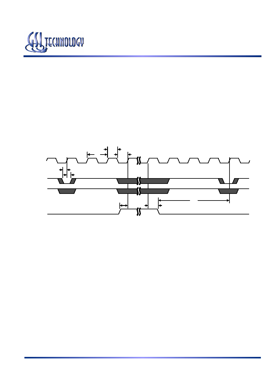
Sleep Mode Timing Diagram
tZZR
tZZH
tZZS
Hold
Setup
tKL
tKH
tKC
CK
ADSP
ADSC
ZZ
Application Tips
Single and Dual Cycle Deselect
SCD devices (like this one) force the use of “dummy read cycles” (read cycles that are launched normally, but that are ended with
the output drivers inactive) in a fully synchronous environment. Dummy read cycles waste performance, but their use usually
assures there will be no bus contention in transitions from reads to writes or between banks of RAMs. DCD SRAMs do not waste
bandwidth on dummy cycles and are logically simpler to manage in a multiple bank application (wait states need not be inserted at
bank address boundary crossings), but greater care must be exercised to avoid excessive bus contention.
JTAG Port Operation
Overview
The JTAG Port on this RAM operates in a manner that is compliant with IEEE Standard 1149.1-1990, a serial boundary scan
interface standard (commonly referred to as JTAG). The JTAG Port input interface levels scale with VDD. The JTAG output
drivers are powered by VDDQ.
Disabling the JTAG Port
It is possible to use this device without utilizing the JTAG port. The port is reset at power-up and will remain inactive unless
clocked. TCK, TDI, and TMS are designed with internal pull-up circuits.To assure normal operation of the RAM with the JTAG
Port unused, TCK, TDI, and TMS may be left floating or tied to either VDD or VSS. TDO should be left unconnected.
相关PDF资料 |
PDF描述 |
|---|---|
| GS88237BD-200T | 256K X 36 CACHE SRAM, 2.7 ns, PBGA165 |
| GS88237CB-200IT | 256K X 36 CACHE SRAM, 2.7 ns, PBGA119 |
| GS882V37BGB-360I | 256K X 36 CACHE SRAM, 1.8 ns, PBGA119 |
| GS9012E/E6 | 500 mA, 20 V, PNP, Si, SMALL SIGNAL TRANSISTOR, TO-226AA |
| GS9012G/E6 | 500 mA, 20 V, PNP, Si, SMALL SIGNAL TRANSISTOR, TO-226AA |
相关代理商/技术参数 |
参数描述 |
|---|---|
| GS88237CB-200 | 制造商:GSI Technology 功能描述:SRAM SYNC DUAL 2.5V/3.3V 9MBIT 256KX36 2.7NS 119FPBGA - Trays |
| GS88237CB-200I | 制造商:GSI Technology 功能描述:SRAM SYNC DUAL 2.5V/3.3V 9MBIT 256KX36 2.7NS 119FPBGA - Trays |
| GS88237CB-200IV | 制造商:GSI Technology 功能描述:SRAM SYNC DUAL 1.8V/2.5V 9MBIT 256KX36 2.5NS 119FPBGA - Trays |
| GS88237CB-200V | 制造商:GSI Technology 功能描述:SRAM SYNC DUAL 1.8V/2.5V 9MBIT 256KX36 2.5NS 119FPBGA - Trays |
| GS88237CB-250 | 制造商:GSI Technology 功能描述:SRAM SYNC DUAL 2.5V/3.3V 9MBIT 256KX36 2.3NS 119FPBGA - Trays |
发布紧急采购,3分钟左右您将得到回复。