- 您现在的位置:买卖IC网 > Datasheet目录328 > IDT7009L20PFI (IDT, Integrated Device Technology Inc)IC SRAM 1MBIT 20NS 100TQFP Datasheet资料下载
参数资料
| 型号: | IDT7009L20PFI |
| 厂商: | IDT, Integrated Device Technology Inc |
| 文件页数: | 16/17页 |
| 文件大小: | 0K |
| 描述: | IC SRAM 1MBIT 20NS 100TQFP |
| 标准包装: | 6 |
| 格式 - 存储器: | RAM |
| 存储器类型: | SRAM - 双端口,异步 |
| 存储容量: | 1M (128K x 8) |
| 速度: | 20ns |
| 接口: | 并联 |
| 电源电压: | 4.5 V ~ 5.5 V |
| 工作温度: | -40°C ~ 85°C |
| 封装/外壳: | 100-LQFP |
| 供应商设备封装: | 100-TQFP(14x14) |
| 包装: | 托盘 |
| 其它名称: | 7009L20PFI |
�� �
�
�IDT7009L�
�High-Speed� 128K� x� 8� Dual-Port� Static� RAM�
�another� task� and� occasionally� attempt� again� to� gain� control� of� the� token� via�
�the� set� and� test� sequence.� Once� the� right� side� has� relinquished� the� token,�
�the� left� side� should� succeed� in� gaining� control.�
�The� semaphore� flags� are� active� LOW.� A� token� is� requested� by� writing�
�a� zero� into� a� semaphore� latch� and� is� released� when� the� same� side� writes�
�a� one� to� that� latch.�
�The� eight� semaphore� flags� reside� within� the� IDT7009� in� a� separate�
�memory� space� from� the� Dual-Port� RAM.� This� address� space� is� accessed�
�by� placing� a� LOW� input� on� the� SEM� pin� (which� acts� as� a� chip� select� for� the�
�semaphore� flags)� and� using� the� other� control� pins� (Address,� CE� ,� and�
�R/� W� )� as� they� would� be� used� in� accessing� a� standard� Static� RAM.� Each�
�of� the� flags� has� a� unique� address� which� can� be� accessed� by� either� side�
�through� address� pins� A� 0� –� A� 2� .� When� accessing� the� semaphores,� none� of�
�Industrial� and� Commercial� Temperature� Ranges�
�side� during� subsequent� read.� Had� a� sequence� of� READ/WRITE� been�
�used� instead,� system� contention� problems� could� have� occurred� during� the�
�gap� between� the� read� and� write� cycles.�
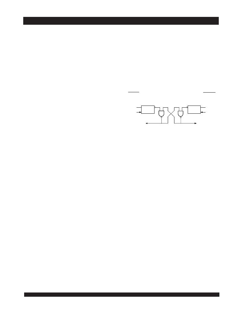
�It� is� important� to� note� that� a� failed� semaphore� request� must� be� followed�
�by� either� repeated� reads� or� by� writing� a� one� into� the� same� location.� The�
�reason� for� this� is� easily� understood� by� looking� at� the� simple� logic� diagram�
�of� the� semaphore� flag� in� Figure� 4.� Two� semaphore� request� latches� feed�
�into� a� semaphore� flag.� Whichever� latch� is� first� to� present� a� zero� to� the�
�semaphore� flag� will� force� its� side� of� the� semaphore� flag� LOW� and� the� other�
�side� HIGH.� This� condition� will� continue� until� a� one� is� written� to� the� same�
�semaphore� request� latch.� Should� the� other� side’s� semaphore� request� latch�
�have� been� written� to� a� zero� in� the� meantime,� the� semaphore� flag� will� flip�
�the� other� address� pins� has� any� effect.�
�When� writing� to� a� semaphore,� only� data� pin� D� 0� is� used.� If� a� LOW� level�
�is� written� into� an� unused� semaphore� location,� that� flag� will� be� set� to� a� zero�
�on� that� side� and� a� one� on� the� other� side� (see� Table� VI).� That� semaphore�
�L� PORT�
�SEMAPHORE�
�REQUEST� FLIP� FLOP�
�R� PORT�
�SEMAPHORE�
�REQUEST� FLIP� FLOP�
�can� now� only� be� modified� by� the� side� showing� the� zero.� When� a� one� is�
�D� 0�
�D�
�Q�
�Q�
�D�
�D� 0�
�written� into� the� same� location� from� the� same� side,� the� flag� will� be� set� to� a�
�one� for� both� sides� (unless� a� semaphore� request� from� the� other� side� is�
�pending)� and� then� can� be� written� to� by� both� sides.� The� fact� that� the� side�
�which� is� able� to� write� a� zero� into� a� semaphore� subsequently� locks� out� writes�
�from� the� other� side� is� what� makes� semaphore� flags� useful� in� interprocessor�
�communications.� (A� thorough� discussion� on� the� use� of� this� feature� follows�
�WRITE�
�SEMAPHORE�
�READ�
�Figure� 4.� IDT7009� Semaphore� Logic�
�WRITE�
�SEMAPHORE�
�READ�
�4839� drw� 18�
�shortly.)� A� zero� written� into� the� same� location� from� the� other� side� will� be�
�stored� in� the� semaphore� request� latch� for� that� side� until� the� semaphore� is�
�freed� by� the� first� side.�
�When� a� semaphore� flag� is� read,� its� value� is� spread� into� all� data� bits� so�
�that� a� flag� that� is� a� one� reads� as� a� one� in� all� data� bits� and� a� flag� containing�
�a� zero� reads� as� all� zeros.� The� read� value� is� latched� into� one� side’s� output�
�register� when� that� side's� semaphore� select� (� SEM� )� and� output� enable� (� OE� )�
�signals� go� active.� This� serves� to� disallow� the� semaphore� from� changing�
�state� in� the� middle� of� a� read� cycle� due� to� a� write� cycle� from� the� other� side.�
�Because� of� this� latch,� a� repeated� read� of� a� semaphore� in� a� test� loop� must�
�cause� either� signal� (� SEM� or� OE� )� to� go� inactive� or� the� output� will� never�
�change.�
�A� sequence� WRITE/READ� must� be� used� by� the� semaphore� in� order�
�to� guarantee� that� no� system� level� contention� will� occur.� A� processor�
�requests� access� to� shared� resources� by� attempting� to� write� a� zero� into� a�
�semaphore� location.� If� the� semaphore� is� already� in� use,� the� semaphore�
�request� latch� will� contain� a� zero,� yet� the� semaphore� flag� will� appear� as� one,�
�a� fact� which� the� processor� will� verify� by� the� subsequent� read� (see� Table�
�VI).� As� an� example,� assume� a� processor� writes� a� zero� to� the� left� port� at�
�a� free� semaphore� location.� On� a� subsequent� read,� the� processor� will� verify�
�that� it� has� written� successfully� to� that� location� and� will� assume� control� over�
�the� resource� in� question.� Meanwhile,� if� a� processor� on� the� right� side�
�attempts� to� write� a� zero� to� the� same� semaphore� flag� it� will� fail,� as� will� be�
�over� to� the� other� side� as� soon� as� a� one� is� written� into� the� first� side’s� request�
�latch.� The� second� side’s� flag� will� now� stay� LOW� until� its� semaphore� request�
�latch� is� written� to� a� one.� From� this� it� is� easy� to� understand� that,� if� a� semaphore�
�is� requested� and� the� processor� which� requested� it� no� longer� needs� the�
�resource,� the� entire� system� can� hang� up� until� a� one� is� written� into� that�
�semaphore� request� latch.�
�The� critical� case� of� semaphore� timing� is� when� both� sides� request� a�
�single� token� by� attempting� to� write� a� zero� into� it� at� the� same� time.� The�
�semaphore� logic� is� specially� designed� to� resolve� this� problem.� If� simulta-�
�neous� requests� are� made,� the� logic� guarantees� that� only� one� side� receives�
�the� token.� If� one� side� is� earlier� than� the� other� in� making� the� request,� the� first�
�side� to� make� the� request� will� receive� the� token.� If� both� requests� arrive� at�
�the� same� time,� the� assignment� will� be� arbitrarily� made� to� one� port� or� the�
�other.�
�One� caution� that� should� be� noted� when� using� semaphores� is� that�
�semaphores� alone� do� not� guarantee� that� access� to� a� resource� is� secure.�
�As� with� any� powerful� programming� technique,� if� semaphores� are� misused�
�or� misinterpreted,� a� software� error� can� easily� happen.�
�Initialization� of� the� semaphores� is� not� automatic� and� must� be� handled�
�via� the� initialization� program� at� power-up.� Since� any� semaphore� request�
�flag� which� contains� a� zero� must� be� reset� to� a� one,� all� semaphores� on� both�
�sides� should� have� a� one� written� into� them� at� initialization� from� both� sides�
�to� assure� that� they� will� be� free� when� needed.�
�verified� by� the� fact� that� a� one� will� be� read� from� that� semaphore� on� the� right�
�16�
�相关PDF资料 |
PDF描述 |
|---|---|
| IDT70125L25JG | IC SRAM 18KBIT 25NS 52PLCC |
| IDT7014S12JG | IC SRAM 36KBIT 12NS 52PLCC |
| IDT7015L35G | IC SRAM 72KBIT 35NS 68PGA |
| IDT7016L35G | IC SRAM 144KBIT 35NS 68PGA |
| IDT7019L20PFI | IC SRAM 1.125MBIT 20NS 100TQFP |
相关代理商/技术参数 |
参数描述 |
|---|---|
| IDT7009L20PFI8 | 功能描述:IC SRAM 1MBIT 20NS 100TQFP RoHS:否 类别:集成电路 (IC) >> 存储器 系列:- 标准包装:1,000 系列:- 格式 - 存储器:RAM 存储器类型:SRAM - 双端口,同步 存储容量:1.125M(32K x 36) 速度:5ns 接口:并联 电源电压:3.15 V ~ 3.45 V 工作温度:-40°C ~ 85°C 封装/外壳:256-LBGA 供应商设备封装:256-CABGA(17x17) 包装:带卷 (TR) 其它名称:70V3579S5BCI8 |
| IDT70101L25J | 制造商:未知厂家 制造商全称:未知厂家 功能描述:x9 Dual-Port SRAM |
| IDT70101L25L52 | 制造商:未知厂家 制造商全称:未知厂家 功能描述:x9 Dual-Port SRAM |
| IDT70101L35J | 制造商:未知厂家 制造商全称:未知厂家 功能描述:x9 Dual-Port SRAM |
| IDT70101L35L52 | 制造商:未知厂家 制造商全称:未知厂家 功能描述:x9 Dual-Port SRAM |
发布紧急采购,3分钟左右您将得到回复。