参数资料
| 型号: | ISL12082IUZ-T |
| 厂商: | Intersil |
| 文件页数: | 5/26页 |
| 文件大小: | 0K |
| 描述: | IC RTC I2C LO-POWER 10-MSOP |
| 标准包装: | 2,500 |
| 类型: | 时钟/日历 |
| 特点: | 警报器,闰年,监视计时器 |
| 时间格式: | HH:MM:SS:hh(12/24 小时) |
| 数据格式: | YY-MM-DD-dd |
| 接口: | I²C,2 线串口 |
| 电源电压: | 2.7 V ~ 5.5 V |
| 电压 - 电源,电池: | 1.8 V ~ 5.5 V |
| 工作温度: | -40°C ~ 85°C |
| 安装类型: | 表面贴装 |
| 封装/外壳: | 10-TFSOP,10-MSOP(0.118",3.00mm 宽) |
| 供应商设备封装: | 10-MSOP |
| 包装: | 带卷 (TR) |
13
FN6731.3
November 24, 2008
default setting of this bit is “0” to enable the backup battery
operation. To use the ReSeal function, simply set RESEAL
bit to “1” after the testing is completed. It will enable the
InterSeal Battery Saver mode and prevents battery current
drain before it is first used. Upon the next VDD powerup, the
bit will reset to “0” and the backup battery will be utilized.
CRYSTAL OSCILLATOR ENABLE BIT (XSTOP)
This bit enables/disables the crystal oscillator. When the
XSTOP is set to “1”, the oscillator is disabled. The XSTOP
bit is set to “0” on power-up for normal operation.
AUTO RESET ENABLE BIT (ARST)
This bit enables/disables the automatic reset of the BAT,
ALM and TMR status bits only. When ARST bit is set to “1”,
these status bits are reset to “0” after a valid read of the
respective status register (with a valid STOP condition).
When the ARST is cleared to “0”, the user must manually
reset the BAT, ALM and TMR bits.
Interrupt Control Register (INT) [Address 08h]
FREQUENCY OUT CONTROL BITS (FO <1:0>)
These bits select the output frequency at the IRQ/fOUT pin.
IRQ1E must be set to “0” for frequency output at the
Note: The falling edge of 1Hz frequency output is
synchronized with the seconds.
IRQ FUNCTION SELECTION BITS (IRQ1E, IRQ2E)
These bits select the function of IRQ1/fOUT and IRQ2 pin.
Table 6 for function selection of IRQ2 pin.
FREQUENCY OUTPUT AND INTERRUPT BIT (FOBATB)
This bit enables/disables the IRQ1/fOUT pin during battery
backup mode (i.e. VBAT power source active). When the
FOBATB is set to “1”, the IRQ1/fOUT pin is disabled during
battery backup mode. This means that both the frequency
output and alarm output functions are disabled. When the
FOBATB is cleared to “0”, the IRQ1/fOUT pin is enabled
during battery backup mode.
LOW POWER MODE BIT (LPMODE)
This bit enables/disables low power mode. With
LPMODE = “0”, the device will be in normal mode and the
VBAT supply will be used when VDD < VBAT - VBATHYS and
VDD < VTRIP. With LPMODE = “1”, the device will be in low
power mode and the VBAT supply will be used when
VDD <VBAT -VBATHYS. There is a supply current saving of
about 600nA when using LPMODE = “1” with VDD = 5V (See
LPMODE ON and OFF). see also “Power Control Operation”
ALARM ENABLE BIT (ALME)
This bit enables/disables the alarm function. When the ALME
bit is set to “1”, the alarm function is enabled. When the ALME
is cleared to “0”, the alarm function is disabled. The alarm
function can operate in either a single event alarm or a periodic
interrupt alarm (see IM bit).
Note: When the frequency output mode is enabled, the alarm
function is disabled.
ALARM PULSE/EVENT INTERRUPT BIT (IM)
This bit enables/disables the interrupt mode of the alarm
function. When the IM bit is set to “1”, the alarm will operate
in the interrupt mode, where an active low pulse width of
210ms will appear at the IRQ1/fOUT and/or IRQ2 pin when
the RTC is triggered by the alarm as defined by the alarm
registers (0Ch to 11h). When the IM bit is cleared to “0”, the
alarm will operate in standard mode, where the IRQ1/FOUT
and/or IRQ2 pin will be tied low until the ALM status bit is
cleared to “0”. The IM bit is set to “0” on power-up.
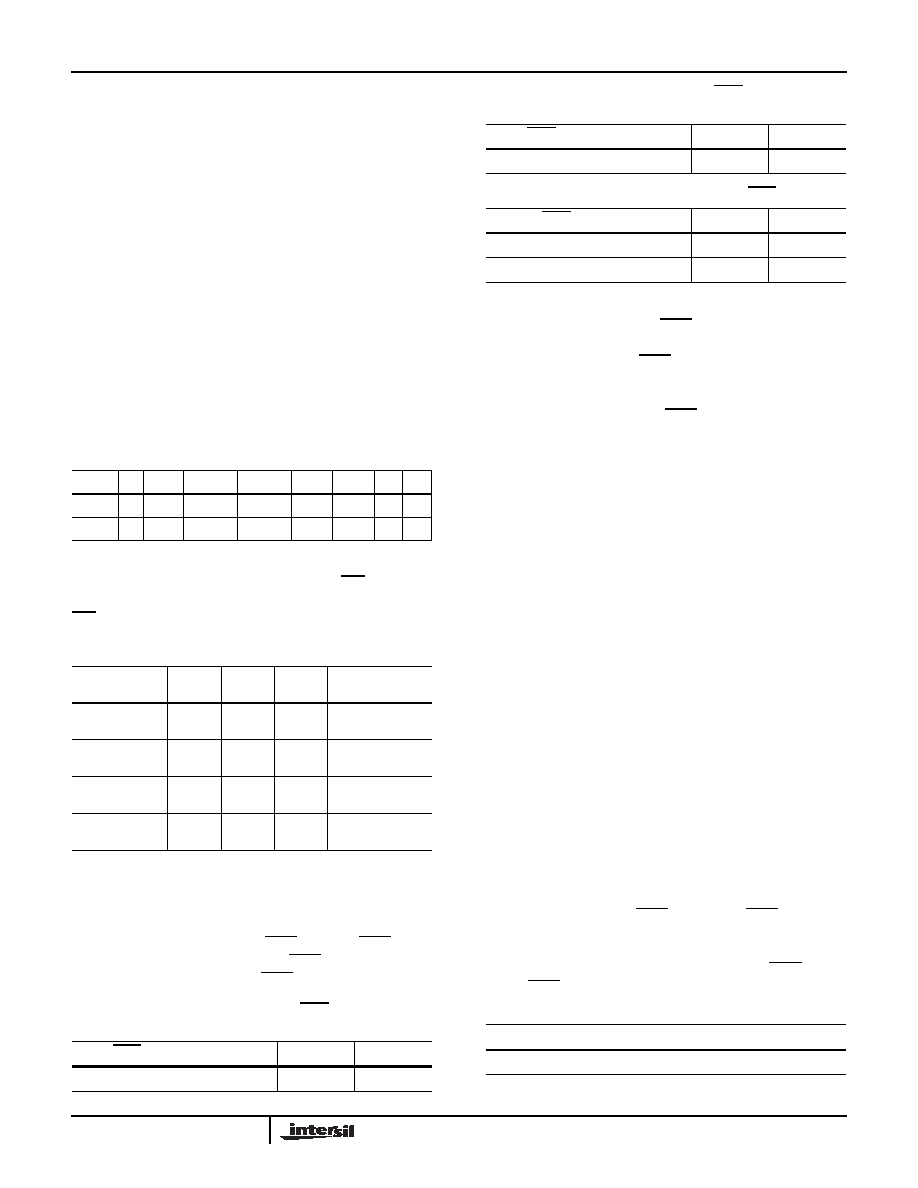
TABLE 3. INTERRUPT CONTROL REGISTER (INT)
ADDR
7
6
5
4
3
2
1
0
08h
IM ALME LPMODE FOBATB IRQ2E IRQ1E FO1 FO0
Default
0
TABLE 4. FREQUENCY SELECTION OF fOUT PIN
FREQUENCY,
fOUT
UNITS
FO1
FO0
COMMENT
32768
Hz
0
Free running
crystal clock
4096
Hz
0
1
Free running
crystal clock
512
Hz
1
0
Free running
crystal clock
1
Hz
1
Sync. with
second, 30s jitter
TABLE 5. FUNCTION SELECTION OF IRQ1/fOUT
PIN
IRQ1/fOUT FUNCTION
IRQ2E
IRQ1E
fOUT
X0
ALARM IRQ
X
1
TABLE 6. FUNCTION SELECTION OF IRQ2 PIN
IRQ2 FUNCTION
IRQ2E
IRQ1E
ALARM IRQ
0
X
TIMER IRQ
1
X
IM BIT
ALARM PULSE/EVENT INTERRUPT FUNCTION
0
Single Time Event Set By Alarm
TABLE 5. FUNCTION SELECTION OF IRQ1/fOUT
PIN (Continued)
IRQ1/fOUT FUNCTION
IRQ2E
IRQ1E
ISL12082
相关PDF资料 |
PDF描述 |
|---|---|
| VI-BN2-MV | CONVERTER MOD DC/DC 15V 150W |
| MS3102A36-8S | CONN RCPT 47POS BOX MNT W/SCKT |
| MS27466T21F11P | CONN RCPT 11POS WALL MT W/PINS |
| ISL23418TFUZ-T7A | IC DGTL POT 1CH 100K 10MSOP |
| D38999/26WH21PA | CONN PLUG 21POS STRAIGHT W/PINS |
相关代理商/技术参数 |
参数描述 |
|---|---|
| ISL1208EVAL | 功能描述:电源管理IC开发工具 EVALRD FOR ISL1208 RoHS:否 制造商:Maxim Integrated 产品:Evaluation Kits 类型:Battery Management 工具用于评估:MAX17710GB 输入电压: 输出电压:1.8 V |
| ISL1208IB8 | 功能描述:IC RTC/CALENDAR I2C 8-SOIC RoHS:否 类别:集成电路 (IC) >> 时钟/计时 - 实时时钟 系列:- 产品培训模块:Obsolescence Mitigation Program 标准包装:1 系列:- 类型:时钟/日历 特点:警报器,闰年,SRAM 存储容量:- 时间格式:HH:MM:SS(12/24 小时) 数据格式:YY-MM-DD-dd 接口:SPI 电源电压:2 V ~ 5.5 V 电压 - 电源,电池:- 工作温度:-40°C ~ 85°C 安装类型:表面贴装 封装/外壳:8-WDFN 裸露焊盘 供应商设备封装:8-TDFN EP 包装:管件 |
| ISL1208IB8-TK | 功能描述:IC RTC/CALENDAR I2C 8-SOIC RoHS:否 类别:集成电路 (IC) >> 时钟/计时 - 实时时钟 系列:- 产品培训模块:Obsolescence Mitigation Program 标准包装:1 系列:- 类型:时钟/日历 特点:警报器,闰年,SRAM 存储容量:- 时间格式:HH:MM:SS(12/24 小时) 数据格式:YY-MM-DD-dd 接口:SPI 电源电压:2 V ~ 5.5 V 电压 - 电源,电池:- 工作温度:-40°C ~ 85°C 安装类型:表面贴装 封装/外壳:8-WDFN 裸露焊盘 供应商设备封装:8-TDFN EP 包装:管件 |
| ISL1208IB8Z | 功能描述:实时时钟 I2C REAL TIME CLOCK/ CALENDAR 8LD RoHS:否 制造商:Microchip Technology 功能:Clock, Calendar. Alarm RTC 总线接口:I2C 日期格式:DW:DM:M:Y 时间格式:HH:MM:SS RTC 存储容量:64 B 电源电压-最大:5.5 V 电源电压-最小:1.8 V 最大工作温度:+ 85 C 最小工作温度: 安装风格:Through Hole 封装 / 箱体:PDIP-8 封装:Tube |
| ISL1208IB8ZR5291 | 功能描述:实时时钟 I2CAL TIME CLK/CLNDR ALL BATRY MODE TESTS RoHS:否 制造商:Microchip Technology 功能:Clock, Calendar. Alarm RTC 总线接口:I2C 日期格式:DW:DM:M:Y 时间格式:HH:MM:SS RTC 存储容量:64 B 电源电压-最大:5.5 V 电源电压-最小:1.8 V 最大工作温度:+ 85 C 最小工作温度: 安装风格:Through Hole 封装 / 箱体:PDIP-8 封装:Tube |
发布紧急采购,3分钟左右您将得到回复。