参数资料
| 型号: | ISL12082IUZ-T |
| 厂商: | Intersil |
| 文件页数: | 6/26页 |
| 文件大小: | 0K |
| 描述: | IC RTC I2C LO-POWER 10-MSOP |
| 标准包装: | 2,500 |
| 类型: | 时钟/日历 |
| 特点: | 警报器,闰年,监视计时器 |
| 时间格式: | HH:MM:SS:hh(12/24 小时) |
| 数据格式: | YY-MM-DD-dd |
| 接口: | I²C,2 线串口 |
| 电源电压: | 2.7 V ~ 5.5 V |
| 电压 - 电源,电池: | 1.8 V ~ 5.5 V |
| 工作温度: | -40°C ~ 85°C |
| 安装类型: | 表面贴装 |
| 封装/外壳: | 10-TFSOP,10-MSOP(0.118",3.00mm 宽) |
| 供应商设备封装: | 10-MSOP |
| 包装: | 带卷 (TR) |
14
FN6731.3
November 24, 2008
Analog Trimming Register (ATR) [Address 0Ah]
ANALOG TRIMMING REGISTER (ATR<5:0>)
Six analog trimming bits, ATR0 to ATR5, are provided in
order to adjust the on-chip load capacitance value for
frequency compensation of the RTC. Each bit has a different
weight for capacitance adjustment. For example, using a
Citizen CFS-206 crystal with different ATR bit combinations
provides an estimated ppm adjustment range from -34ppm
to +80ppm to the nominal frequency compensation. The
combination of analog and digital trimming can give up to
-97ppm to +206ppm of total adjustment.
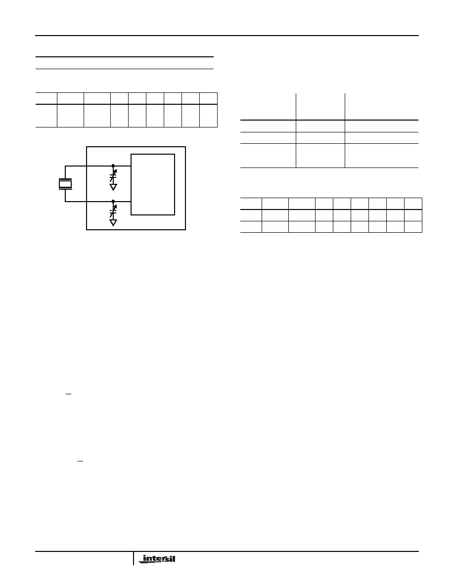
The effective on-chip series load capacitance, CLOAD,
ranges from 4.5pF to 20.25pF with a mid-scale value of
12.5pF (default). CLOAD is changed via two digitally
controlled capacitors, CX1 and CX2, connected from the X1
The effective series load capacitance is the combination of
For example, CLOAD(ATR = 00000) = 12.5pF, CLOAD
(ATR = 100000) = 4.5pF and CLOAD (ATR = 011111) =
20.25pF. The entire range for the series combination of load
capacitance goes from 4.5pF to 20.25pF in 0.25pF steps.
Note that these are typical values.
BATTERY MODE ATR SELECTION (BMATR <1:0>)
Since the accuracy of the crystal oscillator is dependent on
the VDD/VBAT operation, the ISL12082 provides the
capability to adjust the capacitance between VDD and VBAT
when the device switches between power sources.
Digital Trimming Register (DTR) [Address 07h]
DIGITAL TRIMMING REGISTER (DTR<5:0>)
Six digital trimming bits, DTR0 to DTR5, are provided to
adjust the average number of counts per second and
average the ppm error to achieve better accuracy.
DTR5 is a sign bit. DTR5 = “0” means frequency
compensation is < 0. DTR5 = “1” means frequency
compensation is > 0.
DTR<4:0> are scale bits. With DTR5 = “0”, DTR<4:0>
gives 2.0345ppm adjustment per step. With DTR5 = “1”,
DTR<4:0> gives 4.0690ppm adjustment per step.
A range from -63.0696ppm to +126.139ppm can be
represented by using these 6 bits.
For example, with DTR = 11111, the digital adjustment is
(1111b[15d]*4.0690) = +126.139ppm. With DTR = 01111, the
digital adjustment is (-(1111b[15d]*2.0345)) = -63.0696ppm.
Alarm Registers
Addresses [Address 0Ch to 11h]
The alarm register bytes are set up identical to the RTC
register bytes, except that the MSB of each byte functions as
an enable bit (enable = “1”). These enable bits specify which
alarm registers (seconds, minutes, etc) are used to make the
comparison. Note that there is no alarm byte for year and
sub-second, and the register order for alarm register is not a
100% matching to the RTC register so please take caution
on programming the alarm function.
The alarm function works as a comparison between the
alarm registers and the RTC registers. As the RTC
advances, the alarm will be triggered once a match occurs
between the alarm registers and the RTC registers. Any one
1
Repetitive/Recurring Time Event Set By Alarm
TABLE 7. ANALOG TRIMMING REGISTER (ATR)
ADDR
7
6
543210
0Ah
BMATR1 BMATR0 ATR5 ATR4 ATR3 ATR2 ATR1 ATR0
Default
0
000000
IM BIT
ALARM PULSE/EVENT INTERRUPT FUNCTION
FIGURE 11. DIAGRAM OF ATR
CX1
X1
X2
CRYSTAL
OSCILLATOR
CX2
C
X
16 b5
8b4
4 b3
2b2
1 b1
0.5b0
9
+
+
+
+
+
+
()pF
=
(EQ. 1)
C
LOAD
1
C
X1
-----------
1
C
X2
-----------
+
-----------------------------------
=
C
LOAD
16 b5
8 b4
4 b3
2 b2
1 b1
0.5 b0
9
+
+
+
+
+
+
2
-----------------------------------------------------------------------------------------------------------------------------
pF
=
(EQ. 2)
BMATR1
BMATR0
DELTA
CAPACITANCE
(CBAT TO CVDD)
0
0pF
0
1
-0.5pF (
≈ +2ppm)
1
0
+0.5pF (
≈ -2ppm)
1
+1pF (
≈ -4ppm)
TABLE 8. DIGITAL TRIMMING REGISTER (DTR)
ADDR
7
6
543210
07h
0
DTR5 DTR4 DTR3 DTR2 DTR1 DTR0
Default
0
000000
ISL12082
相关PDF资料 |
PDF描述 |
|---|---|
| VI-BN2-MV | CONVERTER MOD DC/DC 15V 150W |
| MS3102A36-8S | CONN RCPT 47POS BOX MNT W/SCKT |
| MS27466T21F11P | CONN RCPT 11POS WALL MT W/PINS |
| ISL23418TFUZ-T7A | IC DGTL POT 1CH 100K 10MSOP |
| D38999/26WH21PA | CONN PLUG 21POS STRAIGHT W/PINS |
相关代理商/技术参数 |
参数描述 |
|---|---|
| ISL1208EVAL | 功能描述:电源管理IC开发工具 EVALRD FOR ISL1208 RoHS:否 制造商:Maxim Integrated 产品:Evaluation Kits 类型:Battery Management 工具用于评估:MAX17710GB 输入电压: 输出电压:1.8 V |
| ISL1208IB8 | 功能描述:IC RTC/CALENDAR I2C 8-SOIC RoHS:否 类别:集成电路 (IC) >> 时钟/计时 - 实时时钟 系列:- 产品培训模块:Obsolescence Mitigation Program 标准包装:1 系列:- 类型:时钟/日历 特点:警报器,闰年,SRAM 存储容量:- 时间格式:HH:MM:SS(12/24 小时) 数据格式:YY-MM-DD-dd 接口:SPI 电源电压:2 V ~ 5.5 V 电压 - 电源,电池:- 工作温度:-40°C ~ 85°C 安装类型:表面贴装 封装/外壳:8-WDFN 裸露焊盘 供应商设备封装:8-TDFN EP 包装:管件 |
| ISL1208IB8-TK | 功能描述:IC RTC/CALENDAR I2C 8-SOIC RoHS:否 类别:集成电路 (IC) >> 时钟/计时 - 实时时钟 系列:- 产品培训模块:Obsolescence Mitigation Program 标准包装:1 系列:- 类型:时钟/日历 特点:警报器,闰年,SRAM 存储容量:- 时间格式:HH:MM:SS(12/24 小时) 数据格式:YY-MM-DD-dd 接口:SPI 电源电压:2 V ~ 5.5 V 电压 - 电源,电池:- 工作温度:-40°C ~ 85°C 安装类型:表面贴装 封装/外壳:8-WDFN 裸露焊盘 供应商设备封装:8-TDFN EP 包装:管件 |
| ISL1208IB8Z | 功能描述:实时时钟 I2C REAL TIME CLOCK/ CALENDAR 8LD RoHS:否 制造商:Microchip Technology 功能:Clock, Calendar. Alarm RTC 总线接口:I2C 日期格式:DW:DM:M:Y 时间格式:HH:MM:SS RTC 存储容量:64 B 电源电压-最大:5.5 V 电源电压-最小:1.8 V 最大工作温度:+ 85 C 最小工作温度: 安装风格:Through Hole 封装 / 箱体:PDIP-8 封装:Tube |
| ISL1208IB8ZR5291 | 功能描述:实时时钟 I2CAL TIME CLK/CLNDR ALL BATRY MODE TESTS RoHS:否 制造商:Microchip Technology 功能:Clock, Calendar. Alarm RTC 总线接口:I2C 日期格式:DW:DM:M:Y 时间格式:HH:MM:SS RTC 存储容量:64 B 电源电压-最大:5.5 V 电源电压-最小:1.8 V 最大工作温度:+ 85 C 最小工作温度: 安装风格:Through Hole 封装 / 箱体:PDIP-8 封装:Tube |
发布紧急采购,3分钟左右您将得到回复。