参数资料
| 型号: | ISL12082IUZ-T |
| 厂商: | Intersil |
| 文件页数: | 9/26页 |
| 文件大小: | 0K |
| 描述: | IC RTC I2C LO-POWER 10-MSOP |
| 标准包装: | 2,500 |
| 类型: | 时钟/日历 |
| 特点: | 警报器,闰年,监视计时器 |
| 时间格式: | HH:MM:SS:hh(12/24 小时) |
| 数据格式: | YY-MM-DD-dd |
| 接口: | I²C,2 线串口 |
| 电源电压: | 2.7 V ~ 5.5 V |
| 电压 - 电源,电池: | 1.8 V ~ 5.5 V |
| 工作温度: | -40°C ~ 85°C |
| 安装类型: | 表面贴装 |
| 封装/外壳: | 10-TFSOP,10-MSOP(0.118",3.00mm 宽) |
| 供应商设备封装: | 10-MSOP |
| 包装: | 带卷 (TR) |
17
FN6731.3
November 24, 2008
Timer Counter Register (TCNT) [Address 13h]
The Timer Counter Register is located in the memory map at
address 13h. This is a volatile register that keeps the current
timer counter value. This byte is read only.
Sub-Timer Initial Register (TSDAT) [Address 14h]
The Sub-Timer Initial Register is located in the memory map
at address 14h. This is a volatile register that stores the
timer limit for the internal sub-timer counter register. This
byte is write only and only read back a “0”
Internal Sub-Timer Counter Register (TSCNT)
The Internal Sub-Timer Counter Register is an internal
volatile register that keeps the current sub-timer counter
value. This byte is not accessible.
Timer Counter Operation
The ISL12082 timer consists of a timer counter and a
sub-timer counter. The timer counter can be an incremental
or a decremental counter which depends on the setting of
the Timer Function Selection Bits (TMOD[1:0], address 09h,
bits 5 and 4). Sub-timer counter works as an incremental
counter. The timer counter is represented by the Timer
Counter Register (TCNT, address 13h) and the sub-timer
counter is represented by the internal Sub-Timer Counter
Register (TSCNT) which is not accessible by the user. The
Timer Initial Register (TDAT, address 12h) and the
Sub-Timer Initial Register (TSDAT, address 14h) are used to
set the limit for the TCNT register and internal TSCNT
register respectively. The TDAT register must contain a
minimum value of 2 in order to operate the timer properly
and the TSAT register can be set to any value up to 127
decimal. If the TSDAT register is set to “0”, the TSDAT will
reset to the default value which depends on the TCLK[1:0]
bits setting which is shown in Table 10.
Once the timer function is enabled by setting the TMRE bit to
“1”, the TCNT register is set to the TDAT value or one
depending on the setting of the TMOD[1:0] bits, and the
internal TSCNT register is set to one. Then the internal
TSCNT will increment one bit at a time and at a frequency
set by the Timer Clock Frequency Selection Bits ( TCLK[1:0],
address 09h bits 1 and 0). The internal TSCNT register will
overflow when it counts up to the value in the TSDAT
register. If the TSDAT register is set to “0”, the internal
TSCNT will count up to the default TSDAT register value to
overflow. If the internal TSCNT register overflows, the TCNT
register will increment or decrement by one depending on
the setting of the TMOD[1:0] bits and the internal TSCNT
register resets back to “1” and repeats the counting cycle.
The timer expires when the TCNT register increments to the
TDAT register value or decrements to zero depending on the
setting of the TMOD[1:0] bits. The TMR bit is set and the
IRQ2 is held low to indicate the timer interrupt. The IRQ2
only activates for the timer interrupt when the IRQ2E
(address 8h, bit 3) sets to “1”.
There are two timer operation modes for the IRQ2: Single
Event and Periodic Interrupt Mode:
Single Event Mode is enabled by setting the TMRE bit to
“1”, the TIM bit to “0”, and IRQ2E bit to “1”. This mode
permits a one-time timer counting cycle. Once the timer
expires, the TMR status bit is set to “1” and the IRQ2 output
will be held low until the TMR status bit is reset to “0”. This
can be done manually or by using the auto-reset feature.
Once the TMR status bit is reset, the timer will reset and
restart the counting cycle. If the TMRE bit is set to “0” before
the TMR status bit is reset, then counting is halted.
The IRQ2 can be reset by setting the TMRE bit to “0” but the
TMR status bit will remain at “1”. The timer can be re-enabled
with TMR status remaining at “1”.
Periodic Interrupt Mode is enabled by setting the TMRE
bit to “1”, the TIM bit to “1”, and IRQ2E bit to “1”. The timer
must be disabled prior to setting TIM bit to “1” in order to
enable the Periodic Interrupt Mode. In the Periodic
Interrupt Mode, the IRQ2 output will be pulsed each time a
timer expires. The low and the high pulse width of the
IRQ2 can be calculated by the TCLK[1:0] bits, the TDAT
register and the TSDAT register. After the interrupt, the
internal TSCNT register will keep counting until it
overflows. When the internal TSCNT register overflows,
the IRQ2 pin is pulled high and the TSCNT register is
reset to the value in TDAT register or “1” depended on the
TMOD[1:0] setting. Then the new counting cycle begins.
The TMR bit is still set each time when the timer expired.
Resetting the TMR status bit to “0” from “1” in the Periodic
Interrupt Mode will cause the TCNT register and the
internal TSCNT register to reset. Depending on when the
TMR bit is being reset, the low pulse width or the high
pulse width will be prolonged for the amount of time the
counter has counted.
The Interrupt Mode can be disabled by setting the TIM bit
to “0” when timer is enabled. The interrupt mode can not
be enabled after the timer is enabled.
When the timer is disabled by setting the TMRE bit to “0”, the
register value for the timer counter and the sub-timer are set
back to the default value. The default value for the Timer
Counter Register (TCNT, address 13h) is “0” and Sub-Timer
Counter Register (TSCNT, address 15h) is “1”.
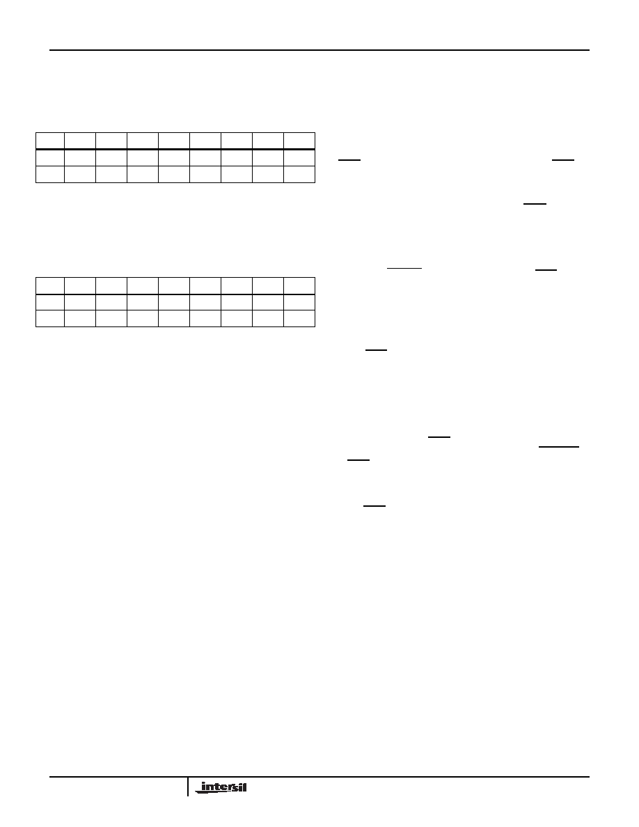
TABLE 13. TIMER COUNTER REGISTER (TCNT)
ADDR
76543210
13h
TCNT7 TCNT6 TCNT5 TCNT4 TCNT3 TCNT2 TCNT1 TCNT0
Default
00000000
TABLE 14. SUB-TIMER INITIAL REGISTER (TSDAT)
ADDR
76543210
14h
TSDAT7 TSDAT6 TSDAT5 TSDAT4 TSDAT3 TSDAT2 TSDAT1 TSDAT0
Default
00000000
ISL12082
相关PDF资料 |
PDF描述 |
|---|---|
| VI-BN2-MV | CONVERTER MOD DC/DC 15V 150W |
| MS3102A36-8S | CONN RCPT 47POS BOX MNT W/SCKT |
| MS27466T21F11P | CONN RCPT 11POS WALL MT W/PINS |
| ISL23418TFUZ-T7A | IC DGTL POT 1CH 100K 10MSOP |
| D38999/26WH21PA | CONN PLUG 21POS STRAIGHT W/PINS |
相关代理商/技术参数 |
参数描述 |
|---|---|
| ISL1208EVAL | 功能描述:电源管理IC开发工具 EVALRD FOR ISL1208 RoHS:否 制造商:Maxim Integrated 产品:Evaluation Kits 类型:Battery Management 工具用于评估:MAX17710GB 输入电压: 输出电压:1.8 V |
| ISL1208IB8 | 功能描述:IC RTC/CALENDAR I2C 8-SOIC RoHS:否 类别:集成电路 (IC) >> 时钟/计时 - 实时时钟 系列:- 产品培训模块:Obsolescence Mitigation Program 标准包装:1 系列:- 类型:时钟/日历 特点:警报器,闰年,SRAM 存储容量:- 时间格式:HH:MM:SS(12/24 小时) 数据格式:YY-MM-DD-dd 接口:SPI 电源电压:2 V ~ 5.5 V 电压 - 电源,电池:- 工作温度:-40°C ~ 85°C 安装类型:表面贴装 封装/外壳:8-WDFN 裸露焊盘 供应商设备封装:8-TDFN EP 包装:管件 |
| ISL1208IB8-TK | 功能描述:IC RTC/CALENDAR I2C 8-SOIC RoHS:否 类别:集成电路 (IC) >> 时钟/计时 - 实时时钟 系列:- 产品培训模块:Obsolescence Mitigation Program 标准包装:1 系列:- 类型:时钟/日历 特点:警报器,闰年,SRAM 存储容量:- 时间格式:HH:MM:SS(12/24 小时) 数据格式:YY-MM-DD-dd 接口:SPI 电源电压:2 V ~ 5.5 V 电压 - 电源,电池:- 工作温度:-40°C ~ 85°C 安装类型:表面贴装 封装/外壳:8-WDFN 裸露焊盘 供应商设备封装:8-TDFN EP 包装:管件 |
| ISL1208IB8Z | 功能描述:实时时钟 I2C REAL TIME CLOCK/ CALENDAR 8LD RoHS:否 制造商:Microchip Technology 功能:Clock, Calendar. Alarm RTC 总线接口:I2C 日期格式:DW:DM:M:Y 时间格式:HH:MM:SS RTC 存储容量:64 B 电源电压-最大:5.5 V 电源电压-最小:1.8 V 最大工作温度:+ 85 C 最小工作温度: 安装风格:Through Hole 封装 / 箱体:PDIP-8 封装:Tube |
| ISL1208IB8ZR5291 | 功能描述:实时时钟 I2CAL TIME CLK/CLNDR ALL BATRY MODE TESTS RoHS:否 制造商:Microchip Technology 功能:Clock, Calendar. Alarm RTC 总线接口:I2C 日期格式:DW:DM:M:Y 时间格式:HH:MM:SS RTC 存储容量:64 B 电源电压-最大:5.5 V 电源电压-最小:1.8 V 最大工作温度:+ 85 C 最小工作温度: 安装风格:Through Hole 封装 / 箱体:PDIP-8 封装:Tube |
发布紧急采购,3分钟左右您将得到回复。