参数资料
| 型号: | ISL62873HRUZ-T |
| 厂商: | Intersil |
| 文件页数: | 14/17页 |
| 文件大小: | 0K |
| 描述: | IC REG CTRLR BUCK PWM 16UTQFN |
| 标准包装: | 3,000 |
| 系列: | Robust Ripple Regulator™ (R³) |
| PWM 型: | 控制器 |
| 输出数: | 1 |
| 频率 - 最大: | 330kHz |
| 电源电压: | 3.3 V ~ 25 V |
| 降压: | 是 |
| 升压: | 无 |
| 回扫: | 无 |
| 反相: | 无 |
| 倍增器: | 无 |
| 除法器: | 无 |
| Cuk: | 无 |
| 隔离: | 无 |
| 工作温度: | -10°C ~ 100°C |
| 封装/外壳: | 16-UFQFN |
| 包装: | 带卷 (TR) |
�� �
�
�ISL62873�
�temperature.� A� saturated� inductor� could� cause� destruction� of�
�circuit� components,� as� well� as� nuisance� OCP� faults.�
�of� the� high-side� MOSFET� and� the� source� of� the� low-side�
�MOSFET.�
�A� DC/DC� buck� regulator� must� have� output� capacitance� C� O�
�into� which� ripple� current� I� P-P� can� flow.� Current� I� P-P� develops�
�a� corresponding� ripple� voltage� V� P-P� across� C� O,� which� is� the�
�sum� of� the� voltage� drop� across� the� capacitor� ESR� and� of� the�
�voltage� change� stemming� from� charge� moved� in� and� out� of�
�the� capacitor.� These� two� voltages� are� expressed� in�
�Equations� 25� and� 26:�
�Δ� V� ESR� =� I� P-P� ?� E� SR�
�(EQ.� 25)�
�0.60�
�0.55�
�0.50�
�0.45�
�0.40�
�0.35�
�0.30�
�0.25�
�x� =� 0.25�
�x=1�
�x� =� 0.75�
�x� =� 0.50�
�Δ� Δ� V� C� =� ---------------------------------�
�I� P-P�
�8� ?� C� O� ?� F� SW�
�(EQ.� 26)�
�0.20�
�0.15�
�0.10�
�x=0�
�If� the� output� of� the� converter� has� to� support� a� load� with� high�
�pulsating� current,� several� capacitors� will� need� to� be� paralleled�
�0.05�
�0�
�0�
�0.1�
�0.2�
�0.3�
�0.4�
�0.5�
�0.6�
�0.7�
�0.8�
�0.9�
�1.0�
�to� reduce� the� total� ESR� until� the� required� V� P-P� is� achieved.� The�
�inductance� of� the� capacitor� can� cause� a� brief� voltage� dip� if� the�
�load� transient� has� an� extremely� high� slew� rate.� Low� inductance�
�capacitors� should� be� considered.� A� capacitor� dissipates� heat� as�
�a� function� of� RMS� current� and� frequency.� Be� sure� that� I� P-P� is�
�shared� by� a� sufficient� quantity� of� paralleled� capacitors� so� that�
�they� operate� below� the� maximum� rated� RMS� current� at� F� SW� .�
�Take� into� account� that� the� rated� value� of� a� capacitor� can� fade�
�as� much� as� 50%� as� the� DC� voltage� across� it� increases.�
�Selection� of� the� Input� Capacitor�
�DUTY� CYCLE�
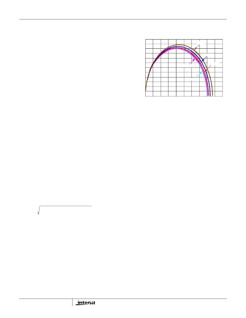
�FIGURE� 10.� NORMALIZED� RMS� INPUT� CURRENT� FOR� x� =� 0.8�
�Selecting� The� Bootstrap� Capacitor�
�Adding� an� external� capacitor� across� the� BOOT� and� PHASE�
�pins� completes� the� bootstrap� circuit.� We� selected� the�
�bootstrap� capacitor� breakdown� voltage� to� be� at� least� 10V.�
�Although� the� theoretical� maximum� voltage� of� the� capacitor� is�
�PVCC-V� DIODE� (voltage� drop� across� the� boot� diode),� large�
�excursions� below� ground� by� the� phase� node� requires� we�
�select� a� capacitor� with� at� least� a� breakdown� rating� of� 10V.� The�
�C� BOOT� ≥� ------------------------�
�The� important� parameters� for� the� bulk� input� capacitance� are�
�the� voltage� rating� and� the� RMS� current� rating.� For� reliable�
�operation,� select� bulk� capacitors� with� voltage� and� current�
�bootstrap� capacitor� can� be� chosen� from� Equation� 29:�
�Q� GATE�
�Δ� V� BOOT�
�(EQ.� 29)�
�(� I� MAX� ?� (� D� –� D� )� )� +� ?� x� ?� I� MAX� ?� ------� ?�
�I� MAX�
�ratings� above� the� maximum� input� voltage� and� capable� of�
�supplying� the� RMS� current� required� by� the� switching� circuit.�
�Their� voltage� rating� should� be� at� least� 1.25x� greater� than� the�
�maximum� input� voltage,� while� a� voltage� rating� of� 1.5x� is� a�
�preferred� rating.� Figure� 10� is� a� graph� of� the� input� RMS� ripple�
�current,� normalized� relative� to� output� load� current,� as� a�
�function� of� duty� cycle� that� is� adjusted� for� converter� efficiency.�
�The� ripple� current� calculation� is� written� as� Equation� 27:�
�2� 2� 2� D�
�?� 12� ?�
�I� IN_RMS� =� -----------------------------------------------------------------------------------------------------� (EQ.� 27)�
�Where:�
�-� I� MAX� is� the� maximum� continuous� I� LOAD� of� the� converter�
�-� x� is� a� multiplier� (0� to� 1)� corresponding� to� the� inductor�
�peak-to-peak� ripple� amplitude� expressed� as� a�
�percentage� of� I� MAX� (0%� to� 100%)�
�-� D� is� the� duty� cycle� that� is� adjusted� to� take� into� account�
�the� efficiency� of� the� converter�
�Duty� cycle� is� written� as� Equation� 28:�
�Where:�
�-� Q� GATE� is� the� amount� of� gate� charge� required� to� fully�
�charge� the� gate� of� the� upper� MOSFET�
�-� Δ� V� BOOT� is� the� maximum� decay� across� the� BOOT�
�capacitor�
�As� an� example,� suppose� an� upper� MOSFET� has� a� gate�
�charge,� Q� GATE� ,� of� 25nC� at� 5V� and� also� assume� the� droop� in�
�the� drive� voltage� over� a� PWM� cycle� is� 200mV.� One� will� find� that�
�a� bootstrap� capacitance� of� at� least� 0.125μF� is� required.� The�
�next� larger� standard� value� capacitance� is� 0.15μF.� A� good�
�quality� ceramic� capacitor� such� as� X7R� or� X5R� is�
�recommended.�
�V� O�
�V� IN� ?� EFF�
�D� =� --------------------------�
�(EQ.� 28)�
�In� addition� to� the� bulk� capacitance,� some� low� ESL� ceramic�
�capacitance� is� recommended� to� decouple� between� the� drain�
�14�
�FN6930.1�
�August� 31,� 2010�
�相关PDF资料 |
PDF描述 |
|---|---|
| ISL62875HRUZ-T | IC REG CTRLR BUCK PWM 20UTQFN |
| ISL62881CIRTZ | IC REG PWM SGL PHASE 28TQFN |
| ISL62881HRTZ | IC REG PWM SGL PHASE 28TQFN |
| ISL62882IRTZ | IC REG PWM 2PHASE BUCK 40TQFN |
| ISL62883IRTZ | IC REG PWM 3PHASE BUCK 40TQFN |
相关代理商/技术参数 |
参数描述 |
|---|---|
| ISL62875 | 制造商:INTERSIL 制造商全称:Intersil Corporation 功能描述:PWM DC/DC Controller with VID Inputs for Portable GPU Core-Voltage Regulator |
| ISL62875HRUZ-T | 功能描述:IC REG CTRLR BUCK PWM 20UTQFN RoHS:是 类别:集成电路 (IC) >> PMIC - 稳压器 - DC DC 切换控制器 系列:Robust Ripple Regulator™ (R³) 产品培训模块:Lead (SnPb) Finish for COTS Obsolescence Mitigation Program 标准包装:2,500 系列:- PWM 型:电流模式 输出数:1 频率 - 最大:275kHz 占空比:50% 电源电压:18 V ~ 110 V 降压:无 升压:无 回扫:无 反相:无 倍增器:无 除法器:无 Cuk:无 隔离:是 工作温度:-40°C ~ 85°C 封装/外壳:8-SOIC(0.154",3.90mm 宽) 包装:带卷 (TR) |
| ISL62881 | 制造商:INTERSIL 制造商全称:Intersil Corporation 功能描述:Single-Phase PWM Regulator for IMVP-6.5? Mobile CPUs and GPUs |
| ISL62881_10 | 制造商:INTERSIL 制造商全称:Intersil Corporation 功能描述:Single-Phase PWM Regulator for IMVP-6.5a?¢ Mobile CPUs and GPUs |
| ISL62881B | 制造商:INTERSIL 制造商全称:Intersil Corporation 功能描述:Single-Phase PWM Regulator for IMVP-6.5? Mobile CPUs and GPUs |
发布紧急采购,3分钟左右您将得到回复。