- 您现在的位置:买卖IC网 > PDF目录15176 > ISL6316CRZ-T (Intersil)IC REG CTRLR BUCK PWM VM 40-QFN PDF资料下载
参数资料
| 型号: | ISL6316CRZ-T |
| 厂商: | Intersil |
| 文件页数: | 13/29页 |
| 文件大小: | 0K |
| 描述: | IC REG CTRLR BUCK PWM VM 40-QFN |
| 标准包装: | 4,000 |
| PWM 型: | 电压模式 |
| 输出数: | 1 |
| 频率 - 最大: | 275kHz |
| 占空比: | 66.7% |
| 电源电压: | 4.75 V ~ 5.25 V |
| 降压: | 是 |
| 升压: | 无 |
| 回扫: | 无 |
| 反相: | 无 |
| 倍增器: | 无 |
| 除法器: | 无 |
| Cuk: | 无 |
| 隔离: | 无 |
| 工作温度: | 0°C ~ 70°C |
| 封装/外壳: | 40-VFQFN 裸露焊盘 |
| 包装: | 带卷 (TR) |
第1页第2页第3页第4页第5页第6页第7页第8页第9页第10页第11页第12页当前第13页第14页第15页第16页第17页第18页第19页第20页第21页第22页第23页第24页第25页第26页第27页第28页第29页
�� �
�
�ISL6316�
�PWM� Operation�
�The� timing� of� each� channel� is� set� by� the� number� of� active�
�channels.� The� default� channel� setting� for� the� ISL6316� is� four.�
�The� switching� cycle� is� defined� as� the� time� between� PWM�
�pulse� termination� signals� of� each� channel.� The� pulse�
�termination� signal� is� an� internally� generated� clock� signal�
�which� triggers� the� falling� edge� of� PWM� signal.� The� cycle� time�
�of� the� pulse� termination� signal� is� the� inverse� of� the� switching�
�frequency� set� by� the� resistor� between� the� FS� pin� and� ground.�
�Each� cycle� begins� when� the� clock� signal� commands� the�
�channel� PWM� signal� to� go� low.� The� PWM� signals� command�
�the� MOSFET� driver� to� turn� on/off� the� channel� MOSFETs.�
�For� 4-channel� operation,� the� channel� firing� order� is� 4-3-2-1:�
�PWM3� pulse� terminates� 1/4� of� a� cycle� after� PWM4,� PWM2�
�output� follows� another� 1/4� of� a� cycle� after� PWM3,� and� PWM1�
�terminates� another� 1/4� of� a� cycle� after� PWM2.� For� 3-channel�
�operation,� the� channel� firing� order� is� 3-2-1.�
�Connecting� PWM4� to� VCC� selects� three� channel� operation�
�and� the� pulse-termination� times� are� spaced� in� 1/3� cycle�
�increments.� If� PWM3� is� connected� to� VCC,� two� channel�
�operation� is� selected� and� the� PWM2� pulse� terminates� 1/2� of� a�
�cycle� later.�
�Once� a� PWM� signal� transitions� low,� it� is� held� low� for� a�
�minimum� of� 1/3� cycle.� This� forced� off� time� is� required� to�
�ensure� an� accurate� current� sample.� Current� sensing� is�
�described� in� the� next� section.� After� the� forced� off� time� expires,�
�the� PWM� output� is� enabled.� The� PWM� output� state� is� driven�
�by� the� position� of� the� error� amplifier� output� signal,� V� COMP� ,�
�minus� the� current� correction� signal� relative� to� the� sawtooth�
�ramp� as� illustrated� in� Figure� 7.� When� the� modified� V� COMP�
�voltage� crosses� the� sawtooth� ramp,� the� PWM� output�
�transitions� high.� The� MOSFET� driver� detects� the� change� in�
�state� of� the� PWM� signal� and� turns� off� the� synchronous�
�MOSFET� and� turns� on� the� upper� MOSFET.� The� PWM� signal�
�will� remain� high� until� the� pulse� termination� signal� marks� the�
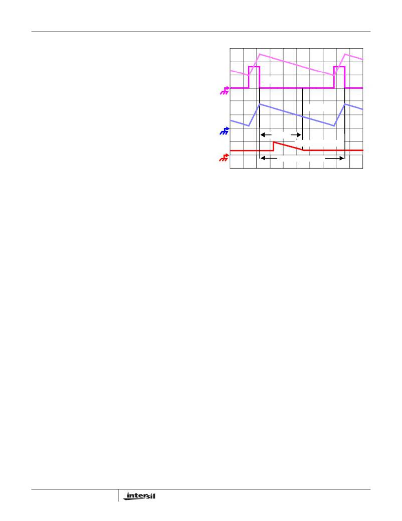
�I� L�
�PWM�
�I� SEN�
�0.5Tsw�
�SAMPLE� CURRENT,� I� n�
�SWITCHING PERIOD�
�TIME�
�FIGURE� 3.� SAMPLE� AND� HOLD� TIMING�
�Current� Sensing�
�The� ISL6316� supports� inductor� DCR� sensing,� MOSFET�
�r� DS(ON)� sensing,� or� resistive� sensing� techniques.� The� internal�
�circuitry,� shown� in� Figures� 4,� 5,� and� 6,� represents� one� channel�
�of� an� N-channel� converter.� This� circuitry� is� repeated� for� each�
�channel� in� the� converter,� but� may� not� be� active� depending� on�
�the� status� of� the� PWM3� and� PWM4� pins,� as� described� in� the�
�PWM� Operation� section.�
�INDUCTOR� DCR� SENSING�
�An� inductor’s� winding� is� characteristic� of� a� distributed�
�resistance� as� measured� by� the� DCR� (Direct� Current�
�Resistance)� parameter.� Consider� the� inductor� DCR� as� a�
�separate� lumped� quantity,� as� shown� in� Figure� 4.� The� channel�
�current� I� L� ,� flowing� through� the� inductor,� will� also� pass� through�
�the� DCR.� Equation� 3� shows� the� s-domain� equivalent� voltage�
�across� the� inductor� V� L� .�
�beginning� of� the� next� cycle� by� triggering� the� PWM� signal� low.�
�Current� Sampling�
�V� L� =� I� L� ?� (� s� ?� L� +� DCR� )�
�(EQ.� 3)�
�During� the� forced� off-time� following� a� PWM� transition� low,� the�
�associated� channel� current� sense� amplifier� uses� the� ISEN�
�inputs� to� reproduce� a� signal� proportional� to� the� inductor�
�current,� I� L� .� This� current� gets� sampled� starting� 1/6� period� after�
�each� PWM� goes� low� and� continuously� gets� sampled� for� 1/3�
�A� simple� R-C� network� across� the� inductor� extracts� the� DCR�
�voltage,� as� shown� in� Figure� 4.�
�The� voltage� on� the� capacitor� V� C� ,� can� be� shown� to� be�
�proportional� to� the� channel� current� I� L� ,� see� Equation� 4.�
�?� s� ?� -------------� +� 1� ?� ?� (� DCR� ?� I� )�
�V� C� =� ---------------------------------------------------------------------�
�period,� or� until� the� PWM� goes� high,� whichever� comes� first.� No�
�matter� the� current� sense� method,� the� sense� current,� I� SEN� ,� is�
�simply� a� scaled� version� of� the� inductor� current.� Coincident�
�with� the� falling� edge� of� the� PWM� signal,� the� sample� and� hold�
�?� DCR� ?� L�
�L�
�(� s� ?� RC� +� 1� )�
�(EQ.� 4)�
�circuitry� samples� the� sensed� current� signal� I� SEN� ,� as� illustrated�
�in� Figure� 3.�
�Therefore,� the� sample� current,� I� n� ,� is� proportional� to� the� output�
�current� and� held� for� one� switching� cycle.� The� sample� current�
�is� used� for� current� balance,� load-line� regulation,� and�
�overcurrent� protection.�
�13�
�If� the� R-C� network� components� are� selected� such� that� the� RC�
�time� constant� (=� R*C)� matches� the� inductor� time� constant�
�(=� L/DCR),� the� voltage� across� the� capacitor� V� C� is� equal� to� the�
�voltage� drop� across� the� DCR,� i.e.� proportional� to� the� channel�
�current.�
�FN9227.1�
�December� 12,� 2006�
�相关PDF资料 |
PDF描述 |
|---|---|
| VI-B4P-EV-F1 | CONVERTER MOD DC/DC 13.8V 150W |
| H2BBT-10112-G8-ND | JUMPER-H1500TR/A3048G/H1500TR12" |
| HIP6301VCBZ-T | IC REG CTRLR BUCK PWM 20-SOIC |
| VI-B4N-EV-F4 | CONVERTER MOD DC/DC 18.5V 150W |
| VI-B4N-EV-F2 | CONVERTER MOD DC/DC 18.5V 150W |
相关代理商/技术参数 |
参数描述 |
|---|---|
| ISL6316IRZ | 功能描述:软开关 PWM 控制器 W/ANNEAL 4-PHS VR11 CNTRLR INDUSTRIAL RoHS:否 制造商:Fairchild Semiconductor 输出端数量: 输出电流: 开关频率: 工作电源电压:30 V 电源电流: 最大工作温度:+ 105 C 最小工作温度:- 40 C 安装风格:SMD/SMT 封装 / 箱体:SOIC-8 封装:Reel |
| ISL6316IRZ-T | 功能描述:软开关 PWM 控制器 W/ANNEAL ISL6306 CNTRLR INDUSTRIAL RoHS:否 制造商:Fairchild Semiconductor 输出端数量: 输出电流: 开关频率: 工作电源电压:30 V 电源电流: 最大工作温度:+ 105 C 最小工作温度:- 40 C 安装风格:SMD/SMT 封装 / 箱体:SOIC-8 封装:Reel |
| ISL6322CRZ | 功能描述:IC CTRLR PWM 4PHASE BUCK 48-QFN RoHS:是 类别:集成电路 (IC) >> PMIC - 稳压器 - 专用型 系列:- 产品培训模块:Lead (SnPb) Finish for COTS Obsolescence Mitigation Program 标准包装:2,000 系列:- 应用:电源,ICERA E400,E450 输入电压:4.1 V ~ 5.5 V 输出数:10 输出电压:可编程 工作温度:-40°C ~ 85°C 安装类型:表面贴装 封装/外壳:42-WFBGA,WLCSP 供应商设备封装:42-WLP 包装:带卷 (TR) |
| ISL6322CRZ-T | 功能描述:IC CTRLR PWM 4PHASE BUCK 48-QFN RoHS:是 类别:集成电路 (IC) >> PMIC - 稳压器 - 专用型 系列:- 产品培训模块:Lead (SnPb) Finish for COTS Obsolescence Mitigation Program 标准包装:2,000 系列:- 应用:电源,ICERA E400,E450 输入电压:4.1 V ~ 5.5 V 输出数:10 输出电压:可编程 工作温度:-40°C ~ 85°C 安装类型:表面贴装 封装/外壳:42-WFBGA,WLCSP 供应商设备封装:42-WLP 包装:带卷 (TR) |
| ISL6322GCRZ | 功能描述:IC CTRLR PWM BUCK 48-QFN RoHS:是 类别:集成电路 (IC) >> PMIC - 稳压器 - 专用型 系列:- 标准包装:2,000 系列:- 应用:控制器,DSP 输入电压:4.5 V ~ 25 V 输出数:2 输出电压:最低可调至 1.2V 工作温度:-40°C ~ 85°C 安装类型:表面贴装 封装/外壳:30-TFSOP(0.173",4.40mm 宽) 供应商设备封装:30-TSSOP 包装:带卷 (TR) |
发布紧急采购,3分钟左右您将得到回复。