参数资料
| 型号: | ISL6564IR-T |
| 厂商: | Intersil |
| 文件页数: | 19/27页 |
| 文件大小: | 0K |
| 描述: | IC REG CTRLR BUCK PWM VM 40-QFN |
| 标准包装: | 4,000 |
| PWM 型: | 电压模式 |
| 输出数: | 1 |
| 频率 - 最大: | 1.5MHz |
| 占空比: | 66.7% |
| 电源电压: | 4.75 V ~ 5.25 V |
| 降压: | 是 |
| 升压: | 无 |
| 回扫: | 无 |
| 反相: | 无 |
| 倍增器: | 无 |
| 除法器: | 无 |
| Cuk: | 无 |
| 隔离: | 无 |
| 工作温度: | -40°C ~ 85°C |
| 封装/外壳: | 40-VFQFN 裸露焊盘 |
| 包装: | 带卷 (TR) |
第1页第2页第3页第4页第5页第6页第7页第8页第9页第10页第11页第12页第13页第14页第15页第16页第17页第18页当前第19页第20页第21页第22页第23页第24页第25页第26页第27页
�� �
�
�ISL6564�
�reoccurs,� the� ISL6564� will� again� command� the� lower�
�PGOOD�
�MOSFETs� to� turn� on.� The� ISL6564� will� continue� to� protect�
�the� load� in� this� fashion� as� long� as� the� overvoltage� condition�
�recurs.�
�UV�
�OC�
�-�
�+�
�110μA�
�I� 1�
�Simultaneous� to� the� protective� action� of� the� PWM� outputs,�
�the� OVP� pin� pulls� to� VCC� delivering� up� to� 100mA� to� the� gate�
�75%�
�REPEAT� FOR�
�EACH� CHANNEL�
�of� a� crowbar� MOSFET� or� SCR� placed� either� on� the� input� rail�
�or� the� output� rail.� Turning� on� the� MOSFET� or� SCR� collapses�
�the� power� rail� and� causes� a� fuse� placed� further� up� stream� to�
�DAC�
�REFERENCE�
�SOFT� START,� FAULT�
�AND� CONTROL� LOGIC�
�-�
�OC�
�+�
�110μA�
�I� AVG�
�blow.� The� fuse� must� be� sized� such� that� the� MOSFET� or� SCR�
�will� not� overheat� before� the� fuse� blows.� The� OVP� pin� is�
�tolerant� to� 12V� (see� Absolute� Maximum� Ratings� ),� so� an�
�external� resistor� pull� up� can� be� used� to� augment� the� driving�
�capability.� If� using� a� pull� up� resistor� in� conjunction� with� the�
�VDIFF�
�+�
�OV�
�OVP�
�internal� overvoltage� protection� function,� care� must� be� taken�
�to� avoid� nuisance� trips� that� could� occur� when� VCC� is� below�
�-�
�VID� +� 0.2V�
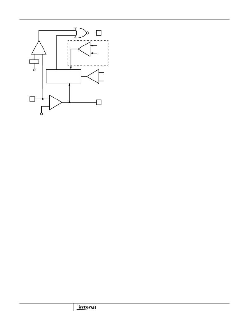
�FIGURE� 12.� POWER� GOOD� AND� PROTECTION� CIRCUITRY�
�Undervoltage� Detection�
�The� undervoltage� threshold� is� set� at� 75%� of� the� VID� code.�
�When� the� output� voltage� at� VSEN� is� below� the� undervoltage�
�threshold,� PGOOD� gets� pulled� low.�
�Overvoltage� Protection�
�When� VCC� is� above� 1.4V,� but� otherwise� not� valid� as� defined�
�under� Power� on� Reset� in� Electrical� Specifications� ,� the�
�overvoltage� trip� circuit� is� active� using� auxiliary� circuitry.� In�
�this� state,� an� overvoltage� trip� occurs� if� the� voltage� at� VSEN�
�exceeds� 1.8V.�
�With� valid� VCC,� the� overvoltage� circuit� is� sensitive� to� the�
�voltage� at� VDIFF.� In� this� state,� the� trip� level� is� 1.7V� prior� to�
�valid� enable� conditions� being� met� as� described� in� Enable�
�and� Disable� .� The� only� exception� to� this� is� when� the� IC� has�
�been� disabled� by� an� overvoltage� trip.� In� that� case� the�
�overvoltage� trip� point� is� VID� plus� 200mV.� During� soft-start,�
�the� overvoltage� trip� level� is� the� higher� of� 1.5V� or� VID� plus�
�200mV.� Upon� successful� soft-start,� the� overvoltage� trip� level�
�is� 200mV� above� VID.� Two� actions� are� taken� by� the� ISL6564�
�to� protect� the� microprocessor� load� when� an� overvoltage�
�condition� occurs.�
�At� the� inception� of� an� overvoltage� event,� all� PWM� outputs�
�are� commanded� low� instantly� (less� than� 20ns)� until� the�
�voltage� at� VSEN� falls� below� 0.6V� with� valid� VCC� or� 1.5V�
�otherwise.� This� causes� the� Intersil� drivers� to� turn� on� the�
�lower� MOSFETs� and� pull� the� output� voltage� below� a� level�
�that� might� cause� damage� to� the� load.� The� PWM� outputs�
�remain� low� until� VDIFF� falls� to� the� programmed� DAC� level�
�when� they� enter� a� high-impedance� state.� The� Intersil� drivers�
�respond� to� the� high-impedance� input� by� turning� off� both�
�upper� and� lower� MOSFETs.� If� the� overvoltage� condition�
�19�
�2V.� In� that� case,� the� controller� is� incapable� of� holding� OVP�
�low.�
�Once� an� overvoltage� condition� is� detected,� normal� PWM�
�operation� ceases� until� the� ISL6564� is� reset.� Cycling� the�
�voltage� on� EN� or� ENLL� or� VCC� below� the� POR-falling�
�threshold� will� reset� the� controller.� Cycling� the� VID� codes� will�
�not� reset� the� controller.�
�Overcurrent� Protection�
�ISL6564� has� two� levels� of� overcurrent� protection.� Each�
�phase� is� protected� from� a� sustained� overcurrent� condition� on�
�a� delayed� basis,� while� the� combined� phase� currents� are�
�protected� on� an� instantaneous� basis.�
�In� instantaneous� protection� mode,� the� ISL6564� takes�
�advantage� of� the� proportionality� between� the� load� current�
�and� the� average� current,� I� AVG� ,� to� detect� an� overcurrent�
�condition.� See� the� Channel-Current� Balance� section� for�
�more� detail� on� how� the� average� current� is� measured.� The�
�average� current� is� continually� compared� with� a� constant�
�110� μ� A� reference� current� as� shown� in� Figure� 10.� Once� the�
�average� current� exceeds� the� reference� current,� a�
�comparator� triggers� the� converter� to� shutdown.�
�In� individual� overcurrent� protection� mode,� the� ISL6564�
�continuously� compares� the� current� of� each� channel� with� the�
�same� 110� μ� A� reference� current.� If� any� channel� current�
�exceeds� the� reference� current� continuously� for� eight�
�consecutive� cycles,� the� comparator� triggers� the� converter� to�
�shutdown.�
�FN9156.2�
�December� 27,� 2004�
�相关PDF资料 |
PDF描述 |
|---|---|
| ISL6565BCV-T | IC REG CTRLR BUCK PWM VM 28TSSOP |
| ISL6566AIRZ | IC CTRLR PWM 3PHASE BUCK 40-QFN |
| ISL6566CRZ-T | IC CTLR PWM BUCK 3PHASE 40-QFN |
| ISL6567CRZ | IC REG CTRLR BUCK PWM VM 24-QFN |
| ISL6568CRZ-T | IC CTLR PWM BUCK 2PHASE 32-QFN |
相关代理商/技术参数 |
参数描述 |
|---|---|
| ISL6564IRZ | 功能描述:电流型 PWM 控制器 MULTI-PHS PWM CNTRLR W/0 525-1 3 VID INDU RoHS:否 制造商:Texas Instruments 开关频率:27 KHz 上升时间: 下降时间: 工作电源电压:6 V to 15 V 工作电源电流:1.5 mA 输出端数量:1 最大工作温度:+ 105 C 安装风格:SMD/SMT 封装 / 箱体:TSSOP-14 |
| ISL6564IRZ-T | 功能描述:电流型 PWM 控制器 MULTI-PHS PWM CNTRLR W/0 525-1 3 VID RoHS:否 制造商:Texas Instruments 开关频率:27 KHz 上升时间: 下降时间: 工作电源电压:6 V to 15 V 工作电源电流:1.5 mA 输出端数量:1 最大工作温度:+ 105 C 安装风格:SMD/SMT 封装 / 箱体:TSSOP-14 |
| ISL6565ACB | 功能描述:IC REG CTRLR BUCK PWM VM 28-SOIC RoHS:否 类别:集成电路 (IC) >> PMIC - 稳压器 - DC DC 切换控制器 系列:- 标准包装:2,500 系列:- PWM 型:电流模式 输出数:1 频率 - 最大:500kHz 占空比:100% 电源电压:8.2 V ~ 30 V 降压:无 升压:无 回扫:是 反相:无 倍增器:无 除法器:无 Cuk:无 隔离:是 工作温度:0°C ~ 70°C 封装/外壳:8-DIP(0.300",7.62mm) 包装:管件 产品目录页面:1316 (CN2011-ZH PDF) |
| ISL6565ACB-T | 功能描述:IC REG CTRLR BUCK PWM VM 28-SOIC RoHS:否 类别:集成电路 (IC) >> PMIC - 稳压器 - DC DC 切换控制器 系列:- 标准包装:2,500 系列:- PWM 型:电流模式 输出数:1 频率 - 最大:500kHz 占空比:100% 电源电压:8.2 V ~ 30 V 降压:无 升压:无 回扫:是 反相:无 倍增器:无 除法器:无 Cuk:无 隔离:是 工作温度:0°C ~ 70°C 封装/外壳:8-DIP(0.300",7.62mm) 包装:管件 产品目录页面:1316 (CN2011-ZH PDF) |
| ISL6565ACBZ | 功能描述:IC REG CTRLR BUCK PWM VM 28-SOIC RoHS:是 类别:集成电路 (IC) >> PMIC - 稳压器 - DC DC 切换控制器 系列:- 产品培训模块:Lead (SnPb) Finish for COTS Obsolescence Mitigation Program 标准包装:2,500 系列:- PWM 型:电流模式 输出数:1 频率 - 最大:275kHz 占空比:50% 电源电压:18 V ~ 110 V 降压:无 升压:无 回扫:无 反相:无 倍增器:无 除法器:无 Cuk:无 隔离:是 工作温度:-40°C ~ 85°C 封装/外壳:8-SOIC(0.154",3.90mm 宽) 包装:带卷 (TR) |
发布紧急采购,3分钟左右您将得到回复。