参数资料
| 型号: | ISL6567CRZ |
| 厂商: | Intersil |
| 文件页数: | 10/25页 |
| 文件大小: | 0K |
| 描述: | IC REG CTRLR BUCK PWM VM 24-QFN |
| 标准包装: | 75 |
| PWM 型: | 电压模式 |
| 输出数: | 1 |
| 频率 - 最大: | 1.5MHz |
| 占空比: | 66% |
| 电源电压: | 4.9 V ~ 5.5 V |
| 降压: | 是 |
| 升压: | 无 |
| 回扫: | 无 |
| 反相: | 无 |
| 倍增器: | 无 |
| 除法器: | 无 |
| Cuk: | 无 |
| 隔离: | 无 |
| 工作温度: | 0°C ~ 70°C |
| 封装/外壳: | 24-VFQFN 裸露焊盘 |
| 包装: | 管件 |
| 产品目录页面: | 1243 (CN2011-ZH PDF) |
�� �
�
�ISL6567�
�(� V� IN� –� N� ?� V� OUT� )� ?� V� OUT�
�L� ?� f� S� ?� V�
�presents� additional� technical� challenges,� the� multi-phase�
�approach� offers� advantages� with� improved� response� time,�
�superior� ripple� cancellation,� and� thermal� distribution.�
�INTERLEAVING�
�The� switching� of� each� channel� in� a� ISL6567-based� converter� is�
�timed� to� be� symmetrically� out-of-phase� with� the� other� channel.�
�As� a� result,� the� two-phase� converter� has� a� combined� ripple�
�frequency� twice� the� frequency� of� one� of� its� phases.� In� addition,�
�the� peak-to-peak� amplitude� of� the� combined� inductor� currents�
�is� proportionately� reduced.� Increased� ripple� frequency� and�
�lower� ripple� amplitude� generally� translate� to� lower� per-channel�
�inductance� and/or� lower� total� output� capacitance� for� any� given�
�set� of� performance� specification.�
�I� PP� =� -------------------------------------------------------------�
�IN�
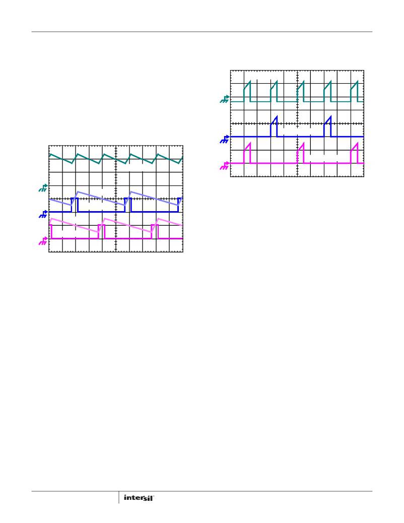
�C� IN� CURRENT�
�Q1 D-S CURRENT�
�(EQ.� 4)�
�Q3 D-S CURRENT�
�I� L1� +� I� L2�
�FIGURE� 4.� INPUT� CAPACITOR� CURRENT� AND� INDIVIDUAL�
�(� V� IN� –� V� OUT� )� ?� V� OUT� (EQ.� 3)�
�L� ?� f� S� ?� V�
�I� L2�
�PWM2�
�I� L1�
�PWM1�
�FIGURE� 3.� PWM� AND� INDUCTOR-CURRENT� WAVEFORMS� FOR�
�2-PHASE� CONVERTER�
�Figure� 3� illustrates� the� additive� effect� on� output� ripple�
�frequency.� The� two� channel� currents� (I� L1� and� I� L2� ),� combine� to�
�form� the� AC� ripple� current� and� the� DC� load� current.� The� ripple�
�component� has� two� times� the� ripple� frequency� of� each�
�individual� channel� current.�
�To� understand� the� reduction� of� ripple� current� amplitude� in� the�
�multi-phase� circuit,� examine� the� equation� representing� an�
�individual� channel’s� peak-to-peak� inductor� current.�
�I� L� ,� PP� =� ---------------------------------------------------�
�IN�
�V� IN� and� V� OUT� are� the� input� and� output� voltages,� respectively,� L�
�is� the� single-channel� inductor� value,� and� f� S� is� the� switching�
�frequency.�
�The� output� capacitors� conduct� the� ripple� component� of� the�
�inductor� current.� In� the� case� of� multi-phase� converters,� the�
�capacitor� current� is� the� sum� of� the� ripple� currents� from� each� of�
�the� individual� channels.� Peak-to-peak� ripple� current� decreases�
�by� an� amount� proportional� to� the� number� of� channels.�
�Output-voltage� ripple� is� a� function� of� capacitance,� capacitor�
�equivalent� series� resistance� (ESR),� and� inductor� ripple� current.�
�Reducing� the� inductor� ripple� current� allows� the� designer� to� use�
�fewer� or� less� costly� output� capacitors� (should� output�
�high-frequency� ripple� be� an� important� design� parameter).�
�10�
�CHANNEL� CURRENTS� IN� A� 2-PHASE� CONVERTER�
�Another� benefit� of� interleaving� is� the� reduction� of� input� ripple�
�current.� Input� capacitance� is� determined� in� a� large� part� by� the�
�maximum� input� ripple� current.� Multi-phase� topologies� can�
�improve� overall� system� cost� and� size� by� lowering� input� ripple�
�current� and� allowing� the� designer� to� reduce� the� cost� of� input�
�capacitance.� The� example� in� Figure� 4� illustrates� input� currents�
�from� a� two-phase� converter� combining� to� reduce� the� total�
�input� ripple� current.�
�Figure� 28,� part� of� the� section� entitled� “Input� Capacitor�
�Selection”� on� page� 24� ,� can� be� used� to� determine� the� input�
�capacitor� RMS� current� based� on� load� current� and� duty� cycle.�
�The� figure� is� provided� as� an� aid� in� determining� the� optimal�
�input� capacitor� solution.�
�PWM� OPERATION�
�One� switching� cycle� for� the� ISL6567� is� defined� as� the� time�
�between� consecutive� PWM� pulse� terminations� (turn-off� of� the�
�upper� MOSFET� on� a� channel).� Each� cycle� begins� when� a�
�switching� clock� signal� commands� the� upper� MOSFET� to� go� off.�
�The� other� channel’s� upper� MOSFET� conduction� is� terminated�
�1/2� of� a� cycle� later.�
�Once� a� channel’s� upper� MOSFET� is� turned� off,� the� lower�
�MOSFET� remains� on� for� a� minimum� of� 1/3� cycle.� This� forced�
�off� time� is� required� to� assure� an� accurate� current� sample.�
�Following� the� 1/3-cycle� forced� off� time,� the� controller� enables�
�the� upper� MOSFET� output.� Once� enabled,� the� upper� MOSFET�
�output� transitions� high� when� the� sawtooth� signal� crosses� the�
�adjusted� error-amplifier� output� signal,� as� illustrated� in�
�Figure� 2.� Just� prior� to� the� upper� drive� turning� the� MOSFET� on,�
�the� lower� MOSFET� drive� turns� the� freewheeling� element� off.�
�The� upper� MOSFET� is� kept� on� until� the� clock� signals� the�
�beginning� of� the� next� switching� cycle� and� the� PWM� pulse� is�
�terminated.�
�CURRENT� SENSING�
�ISL6567� senses� current� by� sampling� the� voltage� across� the�
�lower� MOSFET� during� its� conduction� interval.� MOSFET� r� DS(ON)�
�FN9243.4�
�August� 9,� 2011�
�相关PDF资料 |
PDF描述 |
|---|---|
| ISL6568CRZ-T | IC CTLR PWM BUCK 2PHASE 32-QFN |
| ISL6569ACR-T | IC REG CTRLR BUCK PWM 32-QFN |
| ISL6569CR-T | IC REG CTRLR DIVIDER PWM 32-QFN |
| ISL6571CRZ | IC MOSF DRVR/SYNC SW COMPL 68QFN |
| ISL6611AIRZ | IC REG CTRLR DOUBLER PWM 16-QFN |
相关代理商/技术参数 |
参数描述 |
|---|---|
| ISL6567CRZ-T | 功能描述:IC REG CTRLR BUCK PWM VM 24-QFN RoHS:是 类别:集成电路 (IC) >> PMIC - 稳压器 - DC DC 切换控制器 系列:- 产品培训模块:Lead (SnPb) Finish for COTS Obsolescence Mitigation Program 标准包装:2,500 系列:- PWM 型:电流模式 输出数:1 频率 - 最大:275kHz 占空比:50% 电源电压:18 V ~ 110 V 降压:无 升压:无 回扫:无 反相:无 倍增器:无 除法器:无 Cuk:无 隔离:是 工作温度:-40°C ~ 85°C 封装/外壳:8-SOIC(0.154",3.90mm 宽) 包装:带卷 (TR) |
| ISL6567IRZ | 功能描述:IC REG CTRLR BUCK PWM VM 24-QFN RoHS:是 类别:集成电路 (IC) >> PMIC - 稳压器 - DC DC 切换控制器 系列:- 产品培训模块:Lead (SnPb) Finish for COTS Obsolescence Mitigation Program 标准包装:2,500 系列:- PWM 型:电流模式 输出数:1 频率 - 最大:275kHz 占空比:50% 电源电压:18 V ~ 110 V 降压:无 升压:无 回扫:无 反相:无 倍增器:无 除法器:无 Cuk:无 隔离:是 工作温度:-40°C ~ 85°C 封装/外壳:8-SOIC(0.154",3.90mm 宽) 包装:带卷 (TR) |
| ISL6567IRZS2698 | 功能描述:IC REG CTRLR BUCK PWM VM 24-QFN RoHS:是 类别:集成电路 (IC) >> PMIC - 稳压器 - DC DC 切换控制器 系列:- 产品培训模块:Lead (SnPb) Finish for COTS Obsolescence Mitigation Program 标准包装:2,500 系列:- PWM 型:电流模式 输出数:1 频率 - 最大:275kHz 占空比:50% 电源电压:18 V ~ 110 V 降压:无 升压:无 回扫:无 反相:无 倍增器:无 除法器:无 Cuk:无 隔离:是 工作温度:-40°C ~ 85°C 封装/外壳:8-SOIC(0.154",3.90mm 宽) 包装:带卷 (TR) |
| ISL6567IRZ-T | 功能描述:IC REG CTRLR BUCK PWM VM 24-QFN RoHS:是 类别:集成电路 (IC) >> PMIC - 稳压器 - DC DC 切换控制器 系列:- 产品培训模块:Lead (SnPb) Finish for COTS Obsolescence Mitigation Program 标准包装:2,500 系列:- PWM 型:电流模式 输出数:1 频率 - 最大:275kHz 占空比:50% 电源电压:18 V ~ 110 V 降压:无 升压:无 回扫:无 反相:无 倍增器:无 除法器:无 Cuk:无 隔离:是 工作温度:-40°C ~ 85°C 封装/外壳:8-SOIC(0.154",3.90mm 宽) 包装:带卷 (TR) |
| ISL6567IRZ-TS2698 | 功能描述:IC REG CTRLR BUCK PWM VM 24-QFN RoHS:是 类别:集成电路 (IC) >> PMIC - 稳压器 - DC DC 切换控制器 系列:- 产品培训模块:Lead (SnPb) Finish for COTS Obsolescence Mitigation Program 标准包装:2,500 系列:- PWM 型:电流模式 输出数:1 频率 - 最大:275kHz 占空比:50% 电源电压:18 V ~ 110 V 降压:无 升压:无 回扫:无 反相:无 倍增器:无 除法器:无 Cuk:无 隔离:是 工作温度:-40°C ~ 85°C 封装/外壳:8-SOIC(0.154",3.90mm 宽) 包装:带卷 (TR) |
发布紧急采购,3分钟左右您将得到回复。