- 您现在的位置:买卖IC网 > PDF目录15047 > ISL8103CRZ (Intersil)IC REG CTRLR BUCK PWM VM 40-QFN PDF资料下载
参数资料
| 型号: | ISL8103CRZ |
| 厂商: | Intersil |
| 文件页数: | 10/28页 |
| 文件大小: | 0K |
| 描述: | IC REG CTRLR BUCK PWM VM 40-QFN |
| 标准包装: | 50 |
| PWM 型: | 电压模式 |
| 输出数: | 1 |
| 频率 - 最大: | 1.5MHz |
| 占空比: | 66.6% |
| 电源电压: | 4.75 V ~ 12.6 V |
| 降压: | 是 |
| 升压: | 无 |
| 回扫: | 无 |
| 反相: | 无 |
| 倍增器: | 无 |
| 除法器: | 无 |
| Cuk: | 无 |
| 隔离: | 无 |
| 工作温度: | 0°C ~ 70°C |
| 封装/外壳: | 40-VFQFN 裸露焊盘 |
| 包装: | 管件 |
第1页第2页第3页第4页第5页第6页第7页第8页第9页当前第10页第11页第12页第13页第14页第15页第16页第17页第18页第19页第20页第21页第22页第23页第24页第25页第26页第27页第28页
�� �
�
�ISL8103�
�Another� benefit� of� interleaving� is� to� reduce� input� ripple�
�current.� Input� capacitance� is� determined� in� part� by� the�
�maximum� input� ripple� current.� Multiphase� topologies� can�
�improve� overall� system� cost� and� size� by� lowering� input� ripple�
�current� and� allowing� the� designer� to� reduce� the� cost� of� input�
�capacitance.� The� example� in� Figure� 2� illustrates� input�
�currents� from� a� three-phase� converter� combining� to� reduce�
�the� total� input� ripple� current.�
�The� converter� depicted� in� Figure� 2� delivers� 1.5V� to� a� 36A�
�load� from� a� 12V� input.� The� RMS� input� capacitor� current� is�
�6.1A.� Compare� this� to� a� single-phase� converter� also�
�stepping� down� 12V� to� 1.5V� at� 36A.� The� single-phase�
�converter� has� a� 13.3A� RMS� input� capacitor� current.� The�
�single-phase� converter� must� use� an� input� capacitor� bank�
�with� twice� the� RMS� current� capacity� as� the� equivalent�
�three-phase� converter.�
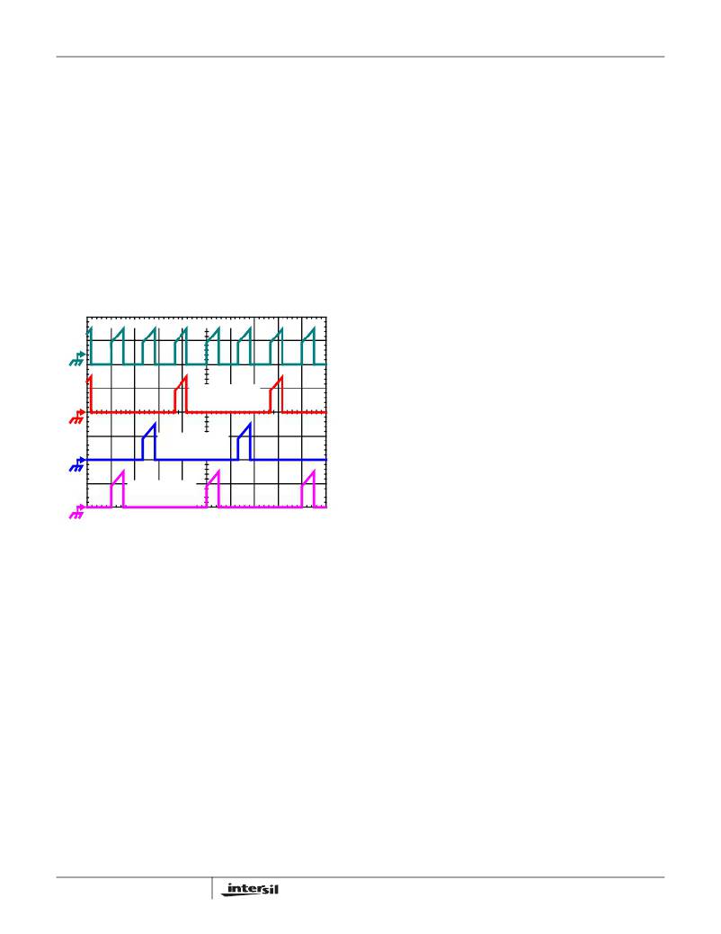
�INPUT-CAPACITOR� CURRENT�
�CHANNEL� 3�
�INPUT� CURRENT�
�CHANNEL� 2�
�INPUT� CURRENT�
�CHANNEL� 1�
�INPUT� CURRENT�
�FIGURE� 2.� CHANNEL� INPUT� CURRENTS� AND� INPUT-�
�CAPACITOR� RMS� CURRENT� FOR� 3-PHASE�
�CONVERTER�
���capacitor� RMS� current� based� on� load� current,� duty� cycle,�
�and� the� number� of� channels.� They� are� provided� as� aids� in�
�determining� the� optimal� input� capacitor� solution.�
�PWM� Operation�
�The� timing� of� each� converter� leg� is� set� by� the� number� of�
�active� channels.� The� default� channel� setting� for� the� ISL8103�
�is� three.� One� switching� cycle� is� defined� as� the� time� between�
�the� internal� PWM1� pulse� termination� signals.� The� pulse�
�termination� signal� is� the� internally� generated� clock� signal�
�that� triggers� the� falling� edge� of� PWM1.� The� cycle� time� of� the�
�pulse� termination� signal� is� the� inverse� of� the� switching�
�frequency� set� by� the� resistor� between� the� FS� pin� and�
�ground.� Each� cycle� begins� when� the� clock� signal� commands�
�PWM1� to� go� low.� The� PWM1� transition� signals� the� internal�
�Channel� 1� MOSFET� driver� to� turn� off� the� Channel� 1� upper�
�MOSFET� and� turn� on� theChannel� 1� synchronous� MOSFET.�
�In� the� default� channel� configuration,� the� PWM2� pulse�
�10�
�terminates� 1/3� of� a� cycle� after� the� PWM1� pulse.� The� PWM3�
�pulse� terminates� 1/3� of� a� cycle� after� PWM2.�
�If� PVCC3� is� left� open� or� connected� to� ground,� two� channel�
�operation� is� selected� and� the� PWM2� pulse� terminates� 1/2� of�
�a� cycle� after� the� PWM1� pulse� terminates.� If� both� PVCC3� and�
�PVCC2� are� left� open� or� connected� to� ground,� single� channel�
�operation� is� selected.� The� 2PH� and� 3PH� inputs� can� also� be�
�used� to� accomplish� this� function.� Once� a� PWM� pulse�
�transitions� low,� it� is� held� low� for� a� minimum� of� 1/3� cycle.� This�
�forced� off� time� is� required� to� ensure� an� accurate� current�
�sample.� Current� sensing� is� described� in� the� next� section.�
�After� the� forced� off� time� expires,� the� PWM� output� is� enabled.�
�The� PWM� output� state� is� driven� by� the� position� of� the� error�
�amplifier� output� signal,� VCOMP,� minus� the� current� correction�
�signal� relative� to� the� sawtooth� ramp� as� illustrated� in� Figure� 3.�
�When� the� modified� VCOMP� voltage� crosses� the� sawtooth�
�ramp,� the� PWM� output� transitions� high.� The� internal�
�MOSFET� driver� detects� the� change� in� state� of� the� PWM�
�signal� and� turns� off� the� synchronous� MOSFET� and� turns� on�
�the� upper� MOSFET.� The� PWM� signal� will� remain� high� until�
�the� pulse� termination� signal� marks� the� beginning� of� the� next�
�cycle� by� triggering� the� PWM� signal� low.�
�Channel� Current� Balance�
�One� important� benefit� of� mulitphase� operation� is� the� thermal�
�advantage� gained� by� distributing� the� dissipated� heat� over�
�multiple� devices� and� greater� area.� By� doing� this� the� designer�
�avoids� the� complexity� of� driving� parallel� MOSFETs� and� the�
�expense� of� using� expensive� heat� sinks� and� exotic� magnetic�
�materials.�
�In� order� to� realize� the� thermal� advantage,� it� is� important� that�
�each� channel� in� a� multiphase� converter� be� controlled� to�
�carry� about� the� same� amount� of� current� at� any� load� level.� To�
�achieve� this,� the� currents� through� each� channel� must� be�
�sampled� every� switching� cycle.� The� sampled� currents,� I� n� ,�
�from� each� active� channel� are� summed� together� and� divided�
�by� the� number� of� active� channels.� The� resulting� cycle�
�average� current,� I� AVG� ,� provides� a� measure� of� the� total� load�
�current� demand� on� the� converter� during� each� switching�
�cycle.� Channel� current� balance� is� achieved� by� comparing�
�the� sampled� current� of� each� channel� to� the� cycle� average�
�current,� and� making� the� proper� adjustment� to� each� channel�
�pulse� width� based� on� the� error.� Intersil’s� patented� current-�
�balance� method� is� illustrated� in� Figure� 3,� with� error�
�correction� for� Channel� 1� represented.� In� the� figure,� the� cycle�
�average� current,� I� AVG� ,� is� compared� with� the� Channel� 1�
�sample,� I� 1� ,� to� create� an� error� signal� I� ER� .�
�The� filtered� error� signal� modifies� the� pulse� width�
�commanded� by� V� COMP� to� correct� any� unbalance� and� force�
�I� ER� toward� zero.� The� same� method� for� error� signal�
�correction� is� applied� to� each� active� channel.�
�FN9246.1�
�July� 21,� 2008�
�相关PDF资料 |
PDF描述 |
|---|---|
| ISL6219ACAZ | IC REG CTRLR BUCK PWM VM 28-QSOP |
| B82464Z4474M | INDUCTOR POWER 470UH .50A SMD |
| H2AXG-10112-Y4-ND | JUMPER-H1503TR/A2015Y/X 12" |
| B82464Z4473M | INDUCTOR POWER 47UH 1.55A SMD |
| H2AXG-10112-W4-ND | JUMPER-H1503TR/A2015W/X 12" |
相关代理商/技术参数 |
参数描述 |
|---|---|
| ISL8103CRZ-T | 功能描述:IC REG CTRLR BUCK PWM VM 40-QFN RoHS:是 类别:集成电路 (IC) >> PMIC - 稳压器 - DC DC 切换控制器 系列:- 标准包装:2,500 系列:- PWM 型:电流模式 输出数:1 频率 - 最大:500kHz 占空比:100% 电源电压:8.2 V ~ 30 V 降压:无 升压:无 回扫:是 反相:无 倍增器:无 除法器:无 Cuk:无 隔离:是 工作温度:0°C ~ 70°C 封装/外壳:8-DIP(0.300",7.62mm) 包装:管件 产品目录页面:1316 (CN2011-ZH PDF) |
| ISL8103EVAL1 | 制造商:INTERSIL 制造商全称:Intersil Corporation 功能描述:Three-Phase Buck PWM Controller with High Current Integrated MOSFET Drivers |
| ISL8103IRZ | 功能描述:IC REG CTRLR BUCK PWM VM 40-QFN RoHS:是 类别:集成电路 (IC) >> PMIC - 稳压器 - DC DC 切换控制器 系列:- 标准包装:2,500 系列:- PWM 型:电流模式 输出数:1 频率 - 最大:500kHz 占空比:100% 电源电压:8.2 V ~ 30 V 降压:无 升压:无 回扫:是 反相:无 倍增器:无 除法器:无 Cuk:无 隔离:是 工作温度:0°C ~ 70°C 封装/外壳:8-DIP(0.300",7.62mm) 包装:管件 产品目录页面:1316 (CN2011-ZH PDF) |
| ISL8103IRZ-T | 功能描述:IC REG CTRLR BUCK PWM VM 40-QFN RoHS:是 类别:集成电路 (IC) >> PMIC - 稳压器 - DC DC 切换控制器 系列:- 标准包装:75 系列:- PWM 型:电流模式 输出数:1 频率 - 最大:1MHz 占空比:81% 电源电压:4.3 V ~ 13.5 V 降压:是 升压:是 回扫:是 反相:无 倍增器:无 除法器:无 Cuk:无 隔离:无 工作温度:0°C ~ 70°C 封装/外壳:8-SOIC(0.154",3.90mm 宽) 包装:管件 产品目录页面:1051 (CN2011-ZH PDF) 其它名称:296-2543-5 |
| ISL8104 | 制造商:INTERSIL 制造商全称:Intersil Corporation 功能描述:Synchronous Buck Pulse-Width Modulator (PWM) Controller |
发布紧急采购,3分钟左右您将得到回复。