- 您现在的位置:买卖IC网 > PDF目录15047 > ISL8103CRZ (Intersil)IC REG CTRLR BUCK PWM VM 40-QFN PDF资料下载
参数资料
| 型号: | ISL8103CRZ |
| 厂商: | Intersil |
| 文件页数: | 20/28页 |
| 文件大小: | 0K |
| 描述: | IC REG CTRLR BUCK PWM VM 40-QFN |
| 标准包装: | 50 |
| PWM 型: | 电压模式 |
| 输出数: | 1 |
| 频率 - 最大: | 1.5MHz |
| 占空比: | 66.6% |
| 电源电压: | 4.75 V ~ 12.6 V |
| 降压: | 是 |
| 升压: | 无 |
| 回扫: | 无 |
| 反相: | 无 |
| 倍增器: | 无 |
| 除法器: | 无 |
| Cuk: | 无 |
| 隔离: | 无 |
| 工作温度: | 0°C ~ 70°C |
| 封装/外壳: | 40-VFQFN 裸露焊盘 |
| 包装: | 管件 |
第1页第2页第3页第4页第5页第6页第7页第8页第9页第10页第11页第12页第13页第14页第15页第16页第17页第18页第19页当前第20页第21页第22页第23页第24页第25页第26页第27页第28页
�� �
�
�ISL8103�
�Current� Balancing� Component� Selection�
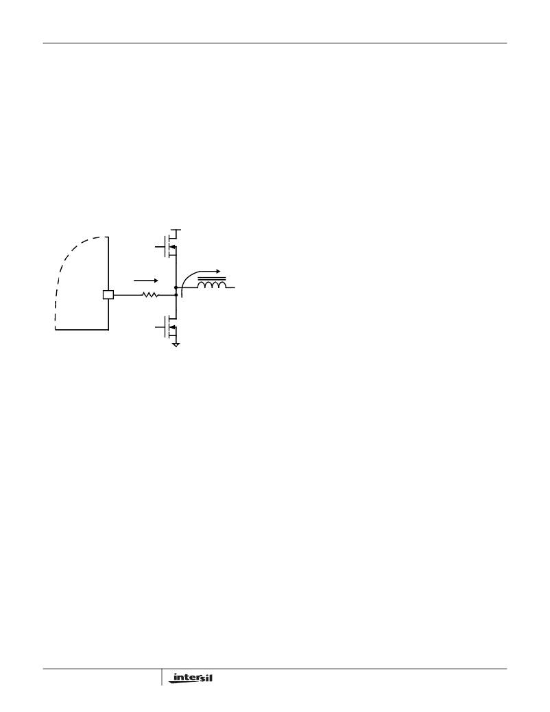
�The� ISL8103� senses� the� channel� load� current� by� sampling�
�the� voltage� across� the� lower� MOSFET� r� DS(ON)� ,� as� shown� in�
�Figure� 17.� The� ISEN� pins� are� denoted� ISEN1,� ISEN2,� and�
�ISEN3.� The� resistors� connected� between� these� pins� and� the�
�respective� phase� nodes� determine� the� gains� in� the� channel�
�current� balance� loop.�
�Select� values� for� these� resistors� based� on� the� room�
�temperature� r� DS(ON)� of� the� lower� MOSFETs;� the� full� load�
�operating� current,� I� FL� ;� and� the� number� of� phases,� N� using�
�Equation� 23.�
�output� inductor� DCR� of� each� channel� (As� described� in�
��illustrates,� an� R-C� network� is� required� to� accurately� sense�
�the� inductor� DCR� voltage� and� convert� this� information� into� a�
�droop� voltage,� which� is� proportional� to� the� total� output�
�current.�
�Choosing� the� components� for� this� current� sense� network� is� a�
�two� step� process.� First,� R� COMP� and� C� COMP� must� be�
�chosen� so� that� the� time� constant� of� this� R� COMP� -C� COMP�
�network� matches� the� time� constant� of� the� inductor� L/DCR.�
�Then� the� resistor� R� S� must� be� chosen� to� set� the� current�
�R� ISEN� =� -----------------------� ?�
�I� FL�
�R� COMP� =� ---------------------------------------�
�r� DS� (� ON� )�
�50� ?� 10� –� 6�
�--------�
�N�
�ISEN(n)�
�R� ISEN�
�V� IN�
�(EQ.� 23)�
�CHANNEL� N�
�UPPER� MOSFET�
�I� L�
�-�
�sense� network� gain,� obtaining� the� desired� full� load� droop�
�voltage.� Follow� the� steps� below� to� choose� the� component�
�values� for� this� R-C� network.�
�1.� Choose� an� arbitrary� value� for� C� COMP� .� The� recommended�
�value� is� 0.01μF.�
�2.� Plug� the� inductor� L� and� DCR� component� values,� and� the�
�values� for� C� COMP� chosen� in� steps� 1,� into� Equation� 25� to�
�calculate� the� value� for� R� COMP� .�
�L�
�(EQ.� 25)�
�DCR� ?� C� COMP�
�3.� Use� the� new� value� for� R� COMP� obtained� from� Equation� 25,�
�as� well� as� the� desired� full� load� current,� I� FL� ,� full� load� droop�
�R� S� =� -------------------------� ?� R� COMP� ?� DCR�
�ISL8103�
�CHANNEL� N�
�LOWER� MOSFET�
�+�
�I� L� x� r� DS� (� ON� )�
�voltage,� V� DROOP� ,� and� inductor� DCR� in� Equation� 26� to�
�calculate� the� value� for� R� S� .�
�I� FL�
�(EQ.� 26)�
�V� DROOP�
�FIGURE� 17.� ISL8103� INTERNAL� AND� EXTERNAL� CURRENT-�
�SENSING� CIRCUITRY�
�In� certain� circumstances,� it� may� be� necessary� to� adjust� the�
�value� of� one� or� more� ISEN� resistors.� When� the� components�
�of� one� or� more� channels� are� inhibited� from� effectively�
�dissipating� their� heat� so� that� the� affected� channels� run� hotter�
�than� desired,� choose� new,� smaller� values� of� R� ISEN� for� the�
��Balance).� Choose� R� ISEN,2� in� proportion� to� the� desired�
�decrease� in� temperature� rise� in� order� to� cause� proportionally�
�less� current� to� flow� in� the� hotter� phase.�
�Due� to� errors� in� the� inductance� or� DCR� it� may� be� necessary�
�to� adjust� the� value� of� R� COMP� to� match� the� time� constants�
�correctly.� The� effects� of� time� constant� mismatch� can� be� seen�
�in� the� form� of� droop� overshoot� or� undershoot� during� the�
�initial� load� transient� spike,� as� shown� in� Figure� 18.� Follow� the�
�steps� below� to� ensure� the� R-C� and� inductor� L/DCR� time�
�constants� are� matched� accurately.�
�1.� Capture� a� transient� event� with� the� oscilloscope� set� to�
�about� L/DCR/2� (sec/div).� For� example,� with� L� =� 1μH� and�
�DCR� =� 1m� Ω� ,� set� the� oscilloscope� to� 500μs/div.�
�R� ISEN� ,� 2� =� R� ISEN� ?� ----------�
�Δ� T� 2�
�Δ� T� 1�
�(EQ.� 24)�
�2.� Record� Δ� V1� and� Δ� V2� as� shown� in� Figure� 18.�
�3.� Select� a� new� value,� R� COMP,2� ,� for� the� time� constant�
�resistor� based� on� the� original� value,� R� COMP,1� ,� using� the�
�R� COMP� ,� 2� =� R� COMP� ,� 1� ?� ----------�
�Δ� V�
�In� Equation� 24,� make� sure� that� Δ� T� 2� is� the� desired�
�temperature� rise� above� the� ambient� temperature,� and� Δ� T� 1� is�
�the� measured� temperature� rise� above� the� ambient�
�temperature.� While� a� single� adjustment� according� to�
�following� equation.�
�Δ� V� 1�
�2�
�(EQ.� 27)�
�Equation� 24� is� usually� sufficient,� it� may� occasionally� be�
�necessary� to� adjust� R� ISEN� two� or� more� times� to� achieve�
�optimal� thermal� balance� between� all� channels.�
�Load� Line� Regulation� Component� Selection� (DCR�
�Current� Sensing)�
�For� accurate� load� line� regulation,� the� ISL8103� senses� the�
�total� output� current� by� detecting� the� voltage� across� the�
�20�
�4.� Replace� R� COMP� with� the� new� value� and� check� to� see� that�
�the� error� is� corrected.� Repeat� the� procedure� if� necessary.�
�After� choosing� a� new� value� for� R� COMP� ,� it� will� most� likely� be�
�necessary� to� adjust� the� value� of� R� S� to� obtain� the� desired� full�
�load� droop� voltage.� Use� Equation� 26� to� obtain� the� new� value�
�for� R� S.�
�FN9246.1�
�July� 21,� 2008�
�相关PDF资料 |
PDF描述 |
|---|---|
| ISL6219ACAZ | IC REG CTRLR BUCK PWM VM 28-QSOP |
| B82464Z4474M | INDUCTOR POWER 470UH .50A SMD |
| H2AXG-10112-Y4-ND | JUMPER-H1503TR/A2015Y/X 12" |
| B82464Z4473M | INDUCTOR POWER 47UH 1.55A SMD |
| H2AXG-10112-W4-ND | JUMPER-H1503TR/A2015W/X 12" |
相关代理商/技术参数 |
参数描述 |
|---|---|
| ISL8103CRZ-T | 功能描述:IC REG CTRLR BUCK PWM VM 40-QFN RoHS:是 类别:集成电路 (IC) >> PMIC - 稳压器 - DC DC 切换控制器 系列:- 标准包装:2,500 系列:- PWM 型:电流模式 输出数:1 频率 - 最大:500kHz 占空比:100% 电源电压:8.2 V ~ 30 V 降压:无 升压:无 回扫:是 反相:无 倍增器:无 除法器:无 Cuk:无 隔离:是 工作温度:0°C ~ 70°C 封装/外壳:8-DIP(0.300",7.62mm) 包装:管件 产品目录页面:1316 (CN2011-ZH PDF) |
| ISL8103EVAL1 | 制造商:INTERSIL 制造商全称:Intersil Corporation 功能描述:Three-Phase Buck PWM Controller with High Current Integrated MOSFET Drivers |
| ISL8103IRZ | 功能描述:IC REG CTRLR BUCK PWM VM 40-QFN RoHS:是 类别:集成电路 (IC) >> PMIC - 稳压器 - DC DC 切换控制器 系列:- 标准包装:2,500 系列:- PWM 型:电流模式 输出数:1 频率 - 最大:500kHz 占空比:100% 电源电压:8.2 V ~ 30 V 降压:无 升压:无 回扫:是 反相:无 倍增器:无 除法器:无 Cuk:无 隔离:是 工作温度:0°C ~ 70°C 封装/外壳:8-DIP(0.300",7.62mm) 包装:管件 产品目录页面:1316 (CN2011-ZH PDF) |
| ISL8103IRZ-T | 功能描述:IC REG CTRLR BUCK PWM VM 40-QFN RoHS:是 类别:集成电路 (IC) >> PMIC - 稳压器 - DC DC 切换控制器 系列:- 标准包装:75 系列:- PWM 型:电流模式 输出数:1 频率 - 最大:1MHz 占空比:81% 电源电压:4.3 V ~ 13.5 V 降压:是 升压:是 回扫:是 反相:无 倍增器:无 除法器:无 Cuk:无 隔离:无 工作温度:0°C ~ 70°C 封装/外壳:8-SOIC(0.154",3.90mm 宽) 包装:管件 产品目录页面:1051 (CN2011-ZH PDF) 其它名称:296-2543-5 |
| ISL8104 | 制造商:INTERSIL 制造商全称:Intersil Corporation 功能描述:Synchronous Buck Pulse-Width Modulator (PWM) Controller |
发布紧急采购,3分钟左右您将得到回复。