- 您现在的位置:买卖IC网 > PDF目录15058 > ISL8103IRZ (Intersil)IC REG CTRLR BUCK PWM VM 40-QFN PDF资料下载
参数资料
| 型号: | ISL8103IRZ |
| 厂商: | Intersil |
| 文件页数: | 21/28页 |
| 文件大小: | 0K |
| 描述: | IC REG CTRLR BUCK PWM VM 40-QFN |
| 标准包装: | 50 |
| PWM 型: | 电压模式 |
| 输出数: | 1 |
| 频率 - 最大: | 1.5MHz |
| 占空比: | 66.6% |
| 电源电压: | 4.75 V ~ 12.6 V |
| 降压: | 是 |
| 升压: | 无 |
| 回扫: | 无 |
| 反相: | 无 |
| 倍增器: | 无 |
| 除法器: | 无 |
| Cuk: | 无 |
| 隔离: | 无 |
| 工作温度: | -40°C ~ 85°C |
| 封装/外壳: | 40-VFQFN 裸露焊盘 |
| 包装: | 管件 |
第1页第2页第3页第4页第5页第6页第7页第8页第9页第10页第11页第12页第13页第14页第15页第16页第17页第18页第19页第20页当前第21页第22页第23页第24页第25页第26页第27页第28页
�� �
�
�ISL8103�
�yields� a� solution� that� is� always� stable� with� very� close� to� ideal�
�transient� performance.�
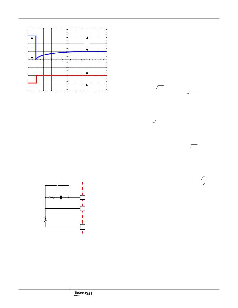
�Δ� V� 1�
�Δ� V� 2�
�V� OUT�
�The� feedback� resistor,� R� 1� ,� has� already� been� chosen� as�
��Select� a� target� bandwidth� for� the� compensated� system,� F� 0� .�
�The� target� bandwidth� must� be� large� enough� to� assure�
�adequate� transient� performance,� but� smaller� than� 1/3� of� the�
�per-channel� switching� frequency.� The� values� of� the�
�compensation� components� depend� on� the� relationships� of�
�F� 0� to� the� L-C� double� pole� frequency� and� the� ESR� zero�
�Δ� I�
�I� TRAN�
�frequency.� For� each� of� the� following� three,� there� is� a�
�separate� set� of� equations� for� the� compensation� components.�
�---------------------------� >� F� 0�
�R� 2� =� R� 1� ?� ------------------------------------------------------------�
�2� π� ?� V� OSC� ?� R� 1� ?� f� 0�
�FIGURE� 18.� TIME� CONSTANT� MISMATCH� BEHAVIOR�
�Compensation�
�The� two� opposing� goals� of� compensating� the� voltage�
�Case� 1:�
�1�
�2� π� ?� L� ?� C�
�2� π� ?� F� 0� ?� V� OSC� ?� L� ?� C�
�0.66� ?� V� IN�
�0.66� ?� V� IN�
�C� 1� =� -------------------------------------------------�
�---------------------------� ≤� F� 0� <� ---------------------------------�
�regulator� are� stability� and� speed.� Depending� on� whether� the�
�regulator� employs� the� optional� load-line� regulation� as�
�Case� 2:�
�1� 1�
�2� π� ?� L� ?� C� 2� π� ?� C� ?� ESR�
�V� OSC� ?� (� 2� π� )� 2� ?� F� 0� ?� L� ?� C�
�C� 1� =� --------------------------------------------------------------------------------�
�(� 2� π� )� ?� F� 0� ?� V� OSC� ?� R� 1� ?� L� ?� C�
�F� 0� >� ---------------------------------�
��there� are� two� distinct� methods� for� achieving� these� goals.�
�Compensating� the� Load-Line� Regulated� Converter�
�The� load-line� regulated� converter� behaves� in� a� similar�
�manner� to� a� peak� current� mode� controller� because� the� two�
�poles� at� the� output� filter� L-C� resonant� frequency� split� with� the�
�introduction� of� current� information� into� the� control� loop.� The�
�final� location� of� these� poles� is� determined� by� the� system�
�2�
�0.66� ?� V�
�R� 2� =� R� 1� ?� ----------------------------------------------------------------�
�IN�
�0.66� ?� V� IN�
�2�
�1�
�2� π� ?� C� ?� ESR�
�(EQ.� 28)�
�R� 2� =� R� 1� ?� -----------------------------------------------�
�2� π� ?� V� OSC� ?� R� 1� ?� F� 0� ?� L�
�function,� the� gain� of� the� current� signal,� and� the� value� of� the�
�compensation� components,� R� 2� and� C� 1� .�
�C� 2� (Optional)�
�Case� 3:�
�2� π� ?� F� 0� ?� V� OSC� ?� L�
�0.66� ?� V� IN� ?� ESR�
�0.66� ?� V� IN� ?� ESR� ?� C�
�C� 2� =� ---------------------------------------------------------------�
�R� 2�
�C� 1�
�COMP�
�In� Equation� 28,� L� is� the� per-channel� filter� inductance� divided�
�by� the� number� of� active� channels;� C� is� the� sum� total� of� all�
�output� capacitors;� ESR� is� the� equivalent� series� resistance� of�
�FB�
�ISL8103�
�the� bulk� output� filter� capacitance;� and� V� PP� is� the� peak-to-�
�peak� sawtooth� signal� amplitude� as� described� in� the�
��R� 1�
�VDIFF�
�FIGURE� 19.� COMPENSATION� CONFIGURATION� FOR�
�LOAD-LINE� REGULATED� ISL8103� CIRCUIT�
�Since� the� system� poles� and� zero� are� affected� by� the� values�
�of� the� components� that� are� meant� to� compensate� them,� the�
�solution� to� the� system� equation� becomes� fairly� complicated.�
�Fortunately,� there� is� a� simple� approximation� that� comes� very�
�close� to� an� optimal� solution.� Treating� the� system� as� though� it�
�were� a� voltage-mode� regulator,� by� compensating� the� L-C�
�poles� and� the� ESR� zero� of� the� voltage� mode� approximation,�
�21�
�Once� selected,� the� compensation� values� in� Equations� 28�
�assure� a� stable� converter� with� reasonable� transient�
�performance.� In� most� cases,� transient� performance� can� be�
�improved� by� making� adjustments� to� R� 2� .� Slowly� increase� the�
�value� of� R� 2� while� observing� the� transient� performance� on� an�
�oscilloscope� until� no� further� improvement� is� noted.� Normally,�
�C� 1� will� not� need� adjustment.� Keep� the� value� of� C� 1� from�
�Equations� 28� unless� some� performance� issue� is� noted.�
�The� optional� capacitor� C� 2� ,� is� sometimes� needed� to� bypass�
�noise� away� from� the� PWM� comparator� (see� Figure� 19).� Keep�
�a� position� available� for� C� 2� ,� and� be� prepared� to� install� a� high�
�frequency� capacitor� of� between� 22pF� and� 150pF� in� case� any�
�leading� edge� jitter� problem� is� noted.�
�FN9246.1�
�July� 21,� 2008�
�相关PDF资料 |
PDF描述 |
|---|---|
| RSM08DTMT-S189 | CONN EDGECARD 16POS R/A .156 SLD |
| ISL6845IU | IC REG CTRLR BST FLYBK ISO 8MSOP |
| ISL6845IB-T | IC REG CTRLR BST FLYBK ISO 8SOIC |
| RGM08DTMT-S189 | CONN EDGECARD 16POS R/A .156 SLD |
| HMM10DRKF | CONN EDGECARD 20POS DIP .156 SLD |
相关代理商/技术参数 |
参数描述 |
|---|---|
| ISL8103IRZ-T | 功能描述:IC REG CTRLR BUCK PWM VM 40-QFN RoHS:是 类别:集成电路 (IC) >> PMIC - 稳压器 - DC DC 切换控制器 系列:- 标准包装:75 系列:- PWM 型:电流模式 输出数:1 频率 - 最大:1MHz 占空比:81% 电源电压:4.3 V ~ 13.5 V 降压:是 升压:是 回扫:是 反相:无 倍增器:无 除法器:无 Cuk:无 隔离:无 工作温度:0°C ~ 70°C 封装/外壳:8-SOIC(0.154",3.90mm 宽) 包装:管件 产品目录页面:1051 (CN2011-ZH PDF) 其它名称:296-2543-5 |
| ISL8104 | 制造商:INTERSIL 制造商全称:Intersil Corporation 功能描述:Synchronous Buck Pulse-Width Modulator (PWM) Controller |
| ISL8104CBZ | 功能描述:IC REG CTRLR BUCK PWM VM 14-SOIC RoHS:是 类别:集成电路 (IC) >> PMIC - 稳压器 - DC DC 切换控制器 系列:- 产品培训模块:Lead (SnPb) Finish for COTS Obsolescence Mitigation Program 标准包装:2,500 系列:- PWM 型:电流模式 输出数:1 频率 - 最大:275kHz 占空比:50% 电源电压:18 V ~ 110 V 降压:无 升压:无 回扫:无 反相:无 倍增器:无 除法器:无 Cuk:无 隔离:是 工作温度:-40°C ~ 85°C 封装/外壳:8-SOIC(0.154",3.90mm 宽) 包装:带卷 (TR) |
| ISL8104CBZ-T | 功能描述:IC REG CTRLR BUCK PWM VM 14-SOIC RoHS:是 类别:集成电路 (IC) >> PMIC - 稳压器 - DC DC 切换控制器 系列:- 产品培训模块:Lead (SnPb) Finish for COTS Obsolescence Mitigation Program 标准包装:2,500 系列:- PWM 型:电流模式 输出数:1 频率 - 最大:275kHz 占空比:50% 电源电压:18 V ~ 110 V 降压:无 升压:无 回扫:无 反相:无 倍增器:无 除法器:无 Cuk:无 隔离:是 工作温度:-40°C ~ 85°C 封装/外壳:8-SOIC(0.154",3.90mm 宽) 包装:带卷 (TR) |
| ISL8104CRZ | 功能描述:IC REG CTRLR BUCK PWM VM 16-QFN RoHS:是 类别:集成电路 (IC) >> PMIC - 稳压器 - DC DC 切换控制器 系列:- 产品培训模块:Lead (SnPb) Finish for COTS Obsolescence Mitigation Program 标准包装:2,500 系列:- PWM 型:电流模式 输出数:1 频率 - 最大:275kHz 占空比:50% 电源电压:18 V ~ 110 V 降压:无 升压:无 回扫:无 反相:无 倍增器:无 除法器:无 Cuk:无 隔离:是 工作温度:-40°C ~ 85°C 封装/外壳:8-SOIC(0.154",3.90mm 宽) 包装:带卷 (TR) |
发布紧急采购,3分钟左右您将得到回复。