- 您现在的位置:买卖IC网 > PDF目录17157 > KITMPR121EVM (Freescale Semiconductor)KIT EVALUATION MPR121 PDF资料下载
参数资料
| 型号: | KITMPR121EVM |
| 厂商: | Freescale Semiconductor |
| 文件页数: | 5/27页 |
| 文件大小: | 0K |
| 描述: | KIT EVALUATION MPR121 |
| 产品培训模块: | MPR121: Low-Power Touch Sensor |
| 标准包装: | 1 |
| 传感器类型: | 近程 |
| 接口: | USB |
| 电源电压: | 5V,USB |
| 嵌入式: | 否 |
| 已供物品: | 4 个板,线缆,文档 |
| 已用 IC / 零件: | MPR121 |
| 产品目录页面: | 2808 (CN2011-ZH PDF) |
第1页第2页第3页第4页当前第5页第6页第7页第8页第9页第10页第11页第12页第13页第14页第15页第16页第17页第18页第19页第20页第21页第22页第23页第24页第25页第26页第27页
MPR121
Sensors
Freescale Semiconductor, Inc.
13
Noise Count Limit (NCL): Determines the number of samples consecutively greater than the Max Half Delta value. This is
necessary to determine that it is not noise. The range of the effective value is 0~255.
Filter Delay Count Limit (FDL): Determines the operation rate of the filter. A larger count limit means the filter delay is operating
more slowly. The range of the effective value is 0~255.
The setting of the filter is depended on the actual application. For more information on these registers, refer to application note
AN3891.
5.6
Touch / Release Threshold (0x41~0x5A)
ExTTH: Electrode touch threshold, in range of 0~0xFF.
ExRTH: Electrode release threshold, in range of 0~0xFF.
Each of the 13 channels can be set with its own set of touch and release thresholds. Touch and release are detected by
comparing the electrode filtered data to the baseline value. The amount of deviation from the baseline value represents a
immediate capacitance change detected by possible a touch/release action.
Touch condition: Baseline - Electrode filtered data > Touch threshold
Release condition: Baseline - Electrode filtered data < Release threshold
Threshold settings are dependant on the touch/release signal strength, system sensitivity and noise immunity requirements. In
a typical touch detection application, threshold is typically in the range 0x04~0x10. The touch threshold is several counts larger
than the release threshold. This is to provide hysteresis and to prevent noise and jitter. For more information, refer to the
application note AN3892 and the MPR121 design guidelines.
5.7
Debounce Register (0x5B)
DT: Debounce number for touch. The value range is 0~7.
DR: Debounce number for release. The value range is 0~7.
All 13 channels use the same set of touch and release debounce numbers. The status bits in Status Register 0x00 and 0x01 will
only take place after the number of consecutive touch or release detection meets the debounce number setting. The debounce
setting can be very useful in avoiding possible noise glitches. Using the debounce setting, the status bit change will have a delay
of {ESI x SFI x DR (or DT)}.
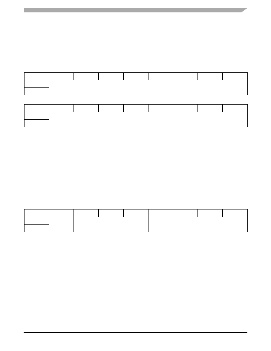
ELEx, ELEProx Touch Threshold (0x41,0x43,...,0x59)
Bit
D7
D6
D5
D4
D3
D2
D1
D0
Read
ExTTH
Write
ELEx, ELEProx Release Threshold (0x42,0x44,...,0x5A)
Bit
D7
D6
D5
D4
D3
D2
D1
D0
Read
ExRTH
Write
Debounce Register (0x5B)
Bit
D7
D6
D5
D4
D3
D2
D1
D0
Read
—
DR
—
DT
Write
相关PDF资料 |
PDF描述 |
|---|---|
| 22R473MC | IND 47UH 0.99A DRUM 7.8X7.5 SMD |
| LB3218T331K | INDUCTOR 330UH 10% 1207 SMD |
| SEK100M160ST | CAP ALUM 10UF 160V 20% RADIAL |
| KITMPR03XEVM | KIT EVAL FOR MPR03X |
| MIC4101YM | IC MOSFET DVR HALF BRIDGE 8-SOIC |
相关代理商/技术参数 |
参数描述 |
|---|---|
| KITMPR121EVM | 制造商:Freescale Semiconductor 功能描述:Sensor Toolbox Proximity Sensor Kit |
| KITMPVZ5004EVK | 功能描述:压力传感器开发工具 WATER LEVEL BOARD RoHS:否 制造商:Freescale Semiconductor 工具用于评估:MPL3115A2 接口类型:USB 最大工作温度: |
| KITMPXA6115AEVB | 功能描述:压力传感器开发工具 Sensor Toolbx Pressu Sensor Developmt brd RoHS:否 制造商:Freescale Semiconductor 工具用于评估:MPL3115A2 接口类型:USB 最大工作温度: |
| KITMPXSHOWEVK | 功能描述:压力传感器开发工具 PRESSURE SHOWBOARD RoHS:否 制造商:Freescale Semiconductor 工具用于评估:MPL3115A2 接口类型:USB 最大工作温度: |
| KITMPXV5004DPEVB | 功能描述:压力传感器开发工具 MPXV5004 Dev Kit RoHS:否 制造商:Freescale Semiconductor 工具用于评估:MPL3115A2 接口类型:USB 最大工作温度: |
发布紧急采购,3分钟左右您将得到回复。