- 您现在的位置:买卖IC网 > PDF目录30743 > LM1253AAE/NA (NATIONAL SEMICONDUCTOR CORP) ON-SCREEN DISPLAY IC, PDIP28 PDF资料下载
参数资料
| 型号: | LM1253AAE/NA |
| 厂商: | NATIONAL SEMICONDUCTOR CORP |
| 元件分类: | 画面叠加 |
| 英文描述: | ON-SCREEN DISPLAY IC, PDIP28 |
| 封装: | 0.600 INCH, PLASTIC, DIP-28 |
| 文件页数: | 60/61页 |
| 文件大小: | 1671K |
| 代理商: | LM1253AAE/NA |
第1页第2页第3页第4页第5页第6页第7页第8页第9页第10页第11页第12页第13页第14页第15页第16页第17页第18页第19页第20页第21页第22页第23页第24页第25页第26页第27页第28页第29页第30页第31页第32页第33页第34页第35页第36页第37页第38页第39页第40页第41页第42页第43页第44页第45页第46页第47页第48页第49页第50页第51页第52页第53页第54页第55页第56页第57页第58页第59页当前第60页第61页
Test Settings
TABLE 1. Control Test Settings
Control
No.
of
Bits
Basic
Test
Setting 1
Basic
Test
Setting 2
Basic
Test
Setting 3
Basic
Test
Setting 4
Contrast
7
Max
(Hex 7F)
Max
(Hex 7F)
Max
(Hex 7F)
Max
(Hex 7F)
R,G,B Gain
7
Max
(Hex 7F)
Max
(Hex 7F)
Set for 1 V
P-P
on all Channels
Max
(Hex 7F)
Brightness
8
Max
(Hex FF)
Max
(Hex FF)
Min
(Hex 00)
Min
(Hex 00)
R,G,B Bias
8
Max
(Hex FF)
Max
(Hex FF)
Min
(Hex 00)
Min
(Hex 00)
DC Offset
3
Min
(Hex 07)
Max
(Hex 00)
Min
(Hex 07)
Min
(Hex 07)
Pedestal Offset
3
Max
(Hex 07)
Max
(Hex 07)
Min
(Hex 00)
Min
(Hex 00)
Pin Descriptions
Pin 1 — R
EXT VREF A10 k 1% resistor is connected to this
pin to set up the internal current sources. The LM1253A is
optimized for this value of resistor. A DC voltage only will be
on this pin. Decreasing the value of this resistor will increase
supply current while degrading performance; increasing the
value of the resistor will decrease supply current and also
degrade the performance. Do not place the resistor close to
sources of heat such as the CRT driver.
Figure 29 shows the
components connected to pin 1,
Figure 11 shows the internal
schematic of pin 1.
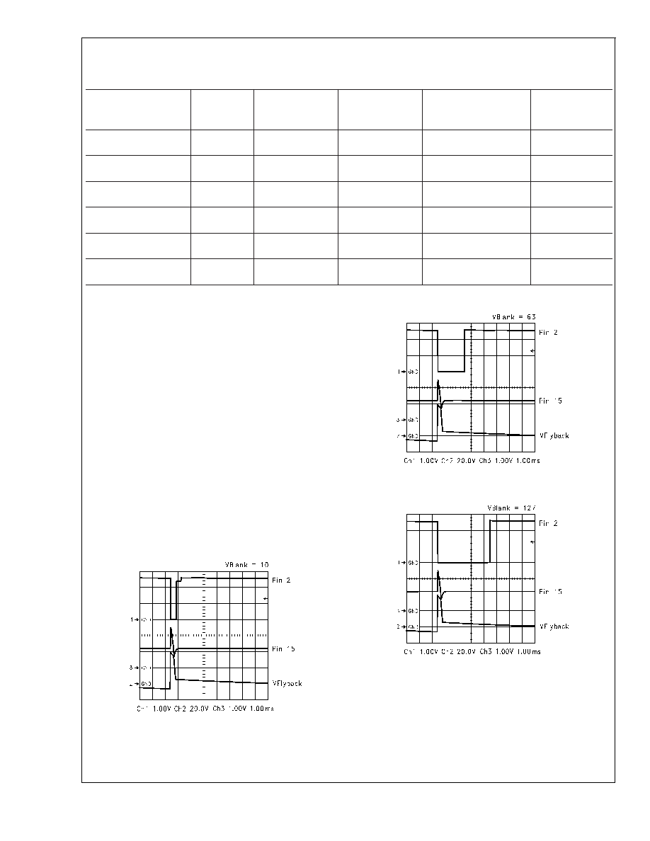
Pin 2 — V Blank Out This pin supplies a variable width,
negative going pulse at the vertical rate to the CRT Driver. V
Blank is triggered from the signal on pin 15, which comes
from the vertical flyback. The CRT Driver supplies the pull up
for this pin. The width of this pulse is set by the value in the
VBLANKDUR register (8403h).
Figures 4, 5, 6 show the
resulting V Blank Out pulse with various values in register
8403h. The trace connecting pin 2 of the LM1253A to the
LM2453 must be kept away from the output circuitry of the
LM2453.
Figure 29 shows the external schematic of pin 2,
Figure 12 shows the internal schematic of pin 2.
Pin 3 — V
REF Cap A 0.1 F capacitor is placed close to this
pin to decouple V
REF.VREF is used by the three video
channel circuits to make the VideoPlex signal.
Figure 29
shows the external schematic of pin 3,
Figure 13 shows the
internal schematic of pin 3.
Pin 4, 5, 6 — Blue, Red, and Green Video In The red, blue,
and green video signal is AC coupled into these pins. The
value of the capacitors is very important as they also serve
DS101265-7
FIGURE 4. V Blank = 10
DS101265-8
FIGURE 5. V Blank = 63
DS101265-9
FIGURE 6. V Blank = 127
LM1253A
www.national.com
8
相关PDF资料 |
PDF描述 |
|---|---|
| LM1267NA/NOPB | 3 CHANNEL, VIDEO PREAMPLIFIER, PDIP24 |
| LM1269NA/NOPB | 3 CHANNEL, VIDEO PREAMPLIFIER, PDIP24 |
| LM1276AAA/NA | 1 CHANNEL, VIDEO PREAMPLIFIER, PDIP28 |
| LM1279AN/NOPB | 3 CHANNEL, VIDEO AMPLIFIER, PDIP20 |
| LM1279N/NOPB | 1 CHANNEL, VIDEO AMPLIFIER, PDIP20 |
相关代理商/技术参数 |
参数描述 |
|---|---|
| LM1253AN | 制造商:NSC 制造商全称:National Semiconductor 功能描述:Monolithic Triple 180 MHz I2C CRT Pre-amp With Integrated Analog On Screen Display (OSD) Generator |
| LM-1256 | 制造商:ROHM 制造商全称:Rohm 功能描述:16 x 16 matrix displays |
| LM-1256_1 | 制造商:ROHM 制造商全称:Rohm 功能描述:16】16 matrix displays |
| LM-1256LB1 | 制造商:ROHM 制造商全称:Rohm 功能描述:16】16 matrix displays |
| LM125AN | 制造商:NSC 制造商全称:National Semiconductor 功能描述:VOLTAGE REGULATORS |
发布紧急采购,3分钟左右您将得到回复。