- 您现在的位置:买卖IC网 > PDF目录1823 > LT1943EFE#TRPBF (Linear Technology)IC REG SW QUAD TFT LCD 28-TSSOP PDF资料下载
参数资料
| 型号: | LT1943EFE#TRPBF |
| 厂商: | Linear Technology |
| 文件页数: | 15/20页 |
| 文件大小: | 0K |
| 描述: | IC REG SW QUAD TFT LCD 28-TSSOP |
| 标准包装: | 2,000 |
| 应用: | 转换器,TFT,LCD |
| 输入电压: | 4.5 V ~ 22 V |
| 输出数: | 4 |
| 输出电压: | 1.25 V ~ 40 V |
| 工作温度: | -40°C ~ 85°C |
| 安装类型: | 表面贴装 |
| 封装/外壳: | 28-SOIC(0.173",4.40mm 宽)裸露焊盘 |
| 供应商设备封装: | 28-TSSOP 裸露焊盘 |
| 包装: | 带卷 (TR) |
�� �
�
�LT1943�
�OPERATIO�
�DC� =�
�|� V� OUT� |�
�V� IN� +� |� V� OUT� |�
�Output� Capacitor� Selection�
�Use� low� ESR� (equivalent� series� resistance)� capacitors� at�
�The� LT1943� can� still� be� used� in� applications� where� the� duty�
�cycle,� as� calculated� above,� is� above� the� maximum.� How-�
�ever,� the� part� must� be� operated� in� discontinuous� mode� so�
�that� the� actual� duty� cycle� is� reduced.�
�Inductor� Selection�
�Several� inductors� that� work� well� with� the� LT1943� regulator�
�are� listed� in� Table� 4.� Besides� these,� many� other� inductors�
�will� work.� Consult� each� manufacturer� for� detailed� informa-�
�tion� and� for� their� entire� selection� of� related� parts.� Use�
�ferrite� core� inductors� to� obtain� the� best� efficiency,� as� core�
�losses� at� frequencies� above� 1MHz� are� much� lower� for�
�ferrite� cores� than� for� powdered-iron� units.� A� 10� μ� H� to� 22� μ� H�
�inductor� will� be� the� best� choice� for� most� LT1943� step-up�
�and� charge� pump� designs.� Choose� an� inductor� that� can�
�carry� the� entire� switch� current� without� saturating.� For�
�inverting� and� SEPIC� regulators,� a� coupled� inductor,� or� two�
�separate� inductors� is� an� option.� When� using� coupled�
�inductors,� choose� one� that� can� handle� at� least� the� switch�
�current� without� saturating.� If� using� uncoupled� inductors,�
�each� inductor� need� only� handle� approximately� one-half� of�
�the� total� switch� current.� A� 4.7� μ� H� to� 15� μ� H� coupled� inductor�
�or� two� 10� μ� H� to� 22� μ� H� uncoupled� inductors� will� usually� be�
�the� best� choice� for� most� LT1943� inverting� and� SEPIC�
�designs.�
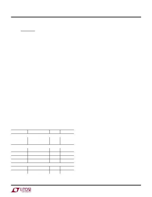
�Table� 4.� Inductors.�
�Part Number Value (� μ� H) I� RMS� (A) DCR (� ?� ) Height (mm)�
�Coiltronics�
�the� output� to� minimize� the� output� ripple� voltage.� Multilayer�
�ceramic� capacitors� are� an� excellent� choice,� as� they� have� an�
�extremely� low� ESR� and� are� available� in� very� small� pack-�
�ages.� X7R� dielectrics� are� preferred,� followed� by� X5R,� as�
�these� materials� retain� their� capacitance� over� wide� voltage�
�and� temperature� ranges.� A� 10� μ� F� to� 22� μ� F� output� capacitor�
�is� sufficient� for� most� LT1943� applications.� Even� less�
�capacitance� is� required� for� outputs� with� |V� OUT� |� >� 20V� or�
�|� I� OUT� |� <� 100mA.� Solid� tantalum� or� OS-CON� capacitors� will�
�also� work,� but� they� will� occupy� more� board� area� and� will�
�have� a� higher� ESR� than� a� ceramic� capacitor.� Always� use� a�
�capacitor� with� a� sufficient� voltage� rating.�
�Diode� Selection�
�A� Schottky� diode� is� recommended� for� use� with� the� LT1943�
�switcher� 2� and� switcher� 4.� The� Schottky� diode� for� switcher�
�3� is� integrated� inside� the� LT1943.� Choose� diodes� for�
�switcher� 2� and� switcher� 4� rated� to� handle� an� average�
�current� greater� than� the� load� current� and� rated� to� handle�
�the� maximum� diode� voltage.� The� average� diode� current� in�
�the� step-up,� SEPIC,� and� inverting� configurations� is� equal�
�to� the� load� current.� Each� of� the� two� diodes� in� the� charge�
�pump� configurations� carries� an� average� diode� current�
�equal� to� the� load� current.� The� maximum� diode� voltage� in�
�the� step-up� and� charge� pump� configurations� is� equal� to�
�|V� OUT� |.� The� maximum� diode� voltage� in� the� SEPIC� and�
�inverting� configurations� is� V� IN� +� |V� OUT� |.�
�Input� Capacitor� Selection�
�TP3-4R7�
�TP4-100�
�4.7�
�10�
�1.5�
�1.5�
�0.181�
�0.146�
�2.2�
�3.0�
�Bypass� the� input� of� the� LT1943� circuit� with� a� 4.7� μ� F� or�
�higher� ceramic� capacitor� of� X7R� or� X5R� type.� A� lower� value�
�Sumida�
�or� a� less� expensive� Y5V� type� will� work� if� there� is� additional�
�CD73-100�
�CDRH5D18-6R2�
�CDRH4D28-100�
�CDRH4D28-100�
�Coilcraft�
�DO3314-103�
�1008PS-103�
�10�
�6.2�
�10�
�10�
�10�
�10�
�1.44�
�1.4�
�1.3�
�1.0�
�0.8�
�0.78�
�0.080�
�0.071�
�0.048�
�0.095�
�0.520�
�0.920�
�3.5�
�2.0�
�3.0�
�3.0�
�1.4�
�2.8�
�bypassing� provided� by� bulk� electrolytic� capacitors� or� if� the�
�input� source� impedance� is� low.� The� following� paragraphs�
�describe� the� input� capacitor� considerations� in� more� detail.�
�Step-down� regulators� draw� current� from� the� input� supply�
�in� pulses� with� very� fast� rise� and� fall� times.� The� input�
�capacitor� is� required� to� reduce� the� resulting� voltage� ripple�
�at� the� LT1943� input� and� to� force� this� switching� current� into�
�a� tight� local� loop,� minimizing� EMI.� The� input� capacitor�
�1943fa�
�15�
�相关PDF资料 |
PDF描述 |
|---|---|
| LT1944-1EMS#TR | IC REG BST ADJ 0.1A/175MA 10MSOP |
| LT1945IMS#TRPBF | IC REG MULTI CONFIG ADJ 10MSOP |
| LT1946EMS8E#TRPBF | IC REG BOOST 1.5A 8MSOP |
| LT1947EMSE#TRPBF | IC REG TFT-LCD ADJ 10-MSOP |
| LT1949IS8#TRPBF | IC REG BOOST ADJ 1A 8SOIC |
相关代理商/技术参数 |
参数描述 |
|---|---|
| LT1944 | 制造商:LINER 制造商全称:Linear Technology 功能描述:Quad DCDC Converter for Triple Outputs TFT Supply Plus LED Driver |
| LT1944-1 | 制造商:LINER 制造商全称:Linear Technology 功能描述:Dual Micropower Step-Up DC/DC Converter |
| LT1944-1EMS | 功能描述:IC REG BST ADJ 0.1A/175MA 10MSOP RoHS:否 类别:集成电路 (IC) >> PMIC - 稳压器 - DC DC 开关稳压器 系列:- 标准包装:2,500 系列:- 类型:升压(升压) 输出类型:可调式 输出数:1 输出电压:1.24 V ~ 30 V 输入电压:1.5 V ~ 12 V PWM 型:电流模式,混合 频率 - 开关:600kHz 电流 - 输出:500mA 同步整流器:无 工作温度:-40°C ~ 85°C 安装类型:表面贴装 封装/外壳:8-SOIC(0.154",3.90mm 宽) 包装:带卷 (TR) 供应商设备封装:8-SOIC |
| LT1944-1EMS#PBF | 功能描述:IC REG BST ADJ 0.1A/175MA 10MSOP RoHS:是 类别:集成电路 (IC) >> PMIC - 稳压器 - DC DC 开关稳压器 系列:- 标准包装:250 系列:- 类型:降压(降压) 输出类型:固定 输出数:1 输出电压:1.2V 输入电压:2.05 V ~ 6 V PWM 型:电压模式 频率 - 开关:2MHz 电流 - 输出:500mA 同步整流器:是 工作温度:-40°C ~ 85°C 安装类型:表面贴装 封装/外壳:6-UFDFN 包装:带卷 (TR) 供应商设备封装:6-SON(1.45x1) 产品目录页面:1032 (CN2011-ZH PDF) 其它名称:296-25628-2 |
| LT1944-1EMS#TR | 功能描述:IC REG BST ADJ 0.1A/175MA 10MSOP RoHS:否 类别:集成电路 (IC) >> PMIC - 稳压器 - DC DC 开关稳压器 系列:- 标准包装:2,500 系列:- 类型:升压(升压) 输出类型:可调式 输出数:1 输出电压:1.24 V ~ 30 V 输入电压:1.5 V ~ 12 V PWM 型:电流模式,混合 频率 - 开关:600kHz 电流 - 输出:500mA 同步整流器:无 工作温度:-40°C ~ 85°C 安装类型:表面贴装 封装/外壳:8-SOIC(0.154",3.90mm 宽) 包装:带卷 (TR) 供应商设备封装:8-SOIC |
发布紧急采购,3分钟左右您将得到回复。