- 您现在的位置:买卖IC网 > PDF目录14838 > LT3487EDD#PBF (Linear Technology)IC REG BOOST INV ADJ 10DFN PDF资料下载
参数资料
| 型号: | LT3487EDD#PBF |
| 厂商: | Linear Technology |
| 文件页数: | 8/16页 |
| 文件大小: | 0K |
| 描述: | IC REG BOOST INV ADJ 10DFN |
| 标准包装: | 121 |
| 类型: | 升压(升压),反相 |
| 输出类型: | 可调式 |
| 输出数: | 1 |
| 输出电压: | 1.23 V ~ 28 V |
| 输入电压: | 2.3 V ~ 16 V |
| PWM 型: | 电流模式 |
| 频率 - 开关: | 2MHz |
| 同步整流器: | 无 |
| 工作温度: | -40°C ~ 85°C |
| 安装类型: | 表面贴装 |
| 封装/外壳: | 10-WFDFN 裸露焊盘 |
| 包装: | 管件 |
| 供应商设备封装: | 10-DFN(3x3) |
| 产品目录页面: | 1331 (CN2011-ZH PDF) |
�� �
�
�LT3487�
�APPLICATIO� S� I� FOR� ATIO�
�Operation�
�The� LT3487� uses� a� constant� frequency,� current� mode� con-�
�trol� scheme� to� provide� excellent� line� and� load� regulation.�
�Operation� can� be� best� understood� by� referring� to� the� Block�
�Diagram� in� Figure� 1.� At� the� start� of� each� oscillator� cycle,�
�the� SR� latch� X1� is� set,� which� turns� on� the� power� switch�
�Q1.� A� voltage� proportional� to� the� switch� current� is� added�
�to� a� stabilizing� ramp� and� the� resulting� sum� is� fed� into� the�
�positive� terminal� of� the� PWM� comparator� A2.� When� this�
�voltage� exceeds� the� level� at� the� negative� input� of� A2,� the�
�SR� latch� X1� is� reset,� turning� off� the� power� switch� Q1.� The�
�level� at� the� negative� input� of� A2� is� set� by� the� error� ampli?er�
�A1,� and� is� simply� an� ampli?ed� version� of� the� difference�
�between� the� feedback� voltage� and� the� reference� voltage�
�of� 1.23V.� In� this� manner,� the� error� ampli?er� sets� the� cor-�
�rect� peak� current� level� to� keep� the� output� in� regulation.�
�If� the� error� ampli?er’s� output� increases,� more� current� is�
�delivered� to� the� output;� if� it� decreases,� less� current� is�
�delivered.� The� second� channel� is� an� inverting� converter.�
�The� basic� operation� is� the� same� as� the� positive� channel.�
�long� as� CAP� is� typically� 1.2V� and� worst-case� 1.6V� (cold)�
�above� the� V� BAT� voltage.� The� drive� current� for� the� output�
�disconnect� PNP� is� returned� to� the� V� BAT� pin.� This� allows�
�the� pass� transistor� to� turn� off� when� the� CAP� voltage�
�falls� to� less� than� 1.2V� above� V� BAT� .� The� V� BAT� pin� allows�
�applications� in� which� the� power� (inductors� L1� and� L2)�
�and� internal� control� circuitry� (V� IN� pin)� are� powered� from�
�different� sources.�
�Inductor� Selection�
�A� 10μH� inductor� is� recommended� for� the� LT3487� boost�
�channel.� The� inverting� channel� can� use� uncoupled� 15μH�
�inductors,� or� coupled� 10μH� inductors.� Small� size� and�
�high� ef?ciency� are� the� major� concerns� for� most� LT3487�
�applications.� Inductors� with� low� core� losses� and� small�
�DCR� (copper� wire� resistance)� at� 2MHz� are� good� choices�
�for� LT3487� applications.� The� inductor� DCR� should� be� on�
�the� order� of� half� of� the� switch� on-resistance� for� its� chan-�
�nel.� Some� inductors� in� this� category� with� small� size� are�
�listed� in� Table� 1.�
�The� SR� latch� X2� is� also� set� at� the� start� of� each� oscillator�
�cycle.� The� power� switch� Q2� is� turned� on� at� the� same� time�
�Table� 1.� Recommended� Inductors�
�CURRENT�
�as� Q1.� Q2� turns� off� based� on� its� own� feedback� loop,� which�
�consists� of� error� ampli?er� A3� and� PWM� comparator� A4.�
�The� reference� voltage� of� this� negative� channel� is� ground.�
�Voltage� clamps� on� V� CP� and� V� CN� (not� shown)� enforce� current�
�PART� NUMBER�
�DB318C-A997AS-�
�100M�
�CDRH3D18-100�
�INDUCTANCE� DCR�
�(μH)� (� Ω� )�
�10� 0.18�
�10� 0.205�
�RATING�
�(mA)� MANUFACTURER�
�580� Toko�
�www.� tokoam.com�
�900� Sumida�
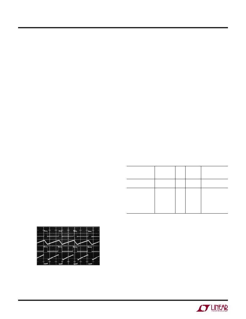
�limit.� Switching� waveforms� with� typical� load� conditions�
�are� shown� in� Figure� 2.�
�The� PNP� Q3� is� used� as� an� output� disconnect� pass� transistor.�
�Q3� disconnects� the� load� from� the� input� during� shutdown.�
�CDRH2D18HP-100�
�CDRH3D23-100�
�CDRH2D18/HP-150�
�CDRH3D18-150�
�CDRH3D23-150�
�10�
�10�
�15�
�15�
�15�
�0.245�
�0.117�
�0.345�
�0.301�
�0.191�
�850�
�850�
�700�
�750�
�700�
�www.sumida.com�
�The� anti-sat� driver� keeps� Q3� at� the� edge� of� saturation� as�
�V� SWP�
�20V/DIV�
�I� LI�
�100mA/DIV�
�V� SWN�
�20V/DIV�
�I� SWN�
�100mA/DIV�
�Capacitor� Selection�
�The� small� size� of� ceramic� capacitors� makes� them� suitable�
�for� LT3487� applications.� X5R� and� X7R� types� of� ceramic�
�capacitors� are� recommended� because� they� retain� their�
�capacitance� over� wider� voltage� and� temperature� ranges�
�than� other� types� such� as� Y5V� or� Z5U.� A� 1μF� input� capaci-�
�tor� is� suf?cient� for� most� LT3487� applications.� The� output�
�capacitors� required� for� stability� depend� on� the� application.�
�V� IN� =� 3.6V�
�V� POS� =� 15V,� 25mA�
�V� NEG� =� –8V,� 50mA�
�200ns/DIV�
�3487� F02�
�For� the� typical� Li-Ion� to� +15V,� –8V� application,� the� positive�
�channel� requires� a� 4.7μF� output� capacitor� and� the� negative�
�Figure� 2.� Switching� Waveforms�
�channel� requires� at� least� 10μF� of� capacitance.�
�3487f�
�8�
�相关PDF资料 |
PDF描述 |
|---|---|
| MAX6463XR43+T | IC VOLT DETECTOR LP SC70-3 |
| ADM660ARZ | IC REG MULTI CONFIG ADJ 8SOIC |
| MAX6463XR35+T | IC VOLT DETECTOR LP SC70-3 |
| PM2120-121K | INDUCTOR TOROID 120UH 10% SMD |
| LTC3419IDD#PBF | IC REG BUCK SYNC ADJ .6A DL 8DFN |
相关代理商/技术参数 |
参数描述 |
|---|---|
| LT3489 | 制造商:LINER 制造商全称:Linear Technology 功能描述:2MHz Boost DC/DC Converter with 2.5A Switch and Soft-Start |
| LT3489EMS8E | 制造商:LINER 制造商全称:Linear Technology 功能描述:2MHz Boost DC/DC Converter with 2.5A Switch and Soft-Start |
| LT3489EMS8E#PBF | 功能描述:IC REG BOOST ADJ 2.5A 8MSOP RoHS:是 类别:集成电路 (IC) >> PMIC - 稳压器 - DC DC 开关稳压器 系列:- 标准包装:250 系列:- 类型:降压(降压) 输出类型:固定 输出数:1 输出电压:1.2V 输入电压:2.05 V ~ 6 V PWM 型:电压模式 频率 - 开关:2MHz 电流 - 输出:500mA 同步整流器:是 工作温度:-40°C ~ 85°C 安装类型:表面贴装 封装/外壳:6-UFDFN 包装:带卷 (TR) 供应商设备封装:6-SON(1.45x1) 产品目录页面:1032 (CN2011-ZH PDF) 其它名称:296-25628-2 |
| LT3489EMS8E#PBF | 制造商:Linear Technology 功能描述:DC-DC CONVERTER BOOST 2MHZ 制造商:Linear Technology 功能描述:DC-DC CONVERTER, BOOST, 2MHZ, MSOP-8 |
| LT3489EMS8E#TR | 制造商:Linear Technology 功能描述:SP-SWREG/Monolithic, 2.5A, 2MHz Step-Up Regulator in MS8E |
发布紧急采购,3分钟左右您将得到回复。