- 您现在的位置:买卖IC网 > PDF目录79850 > LT3757MPMSE#PBF (LINEAR TECHNOLOGY CORP) SWITCHING REGULATOR, 1000 kHz SWITCHING FREQ-MAX, PDSO10 PDF资料下载
参数资料
| 型号: | LT3757MPMSE#PBF |
| 厂商: | LINEAR TECHNOLOGY CORP |
| 元件分类: | 稳压器 |
| 英文描述: | SWITCHING REGULATOR, 1000 kHz SWITCHING FREQ-MAX, PDSO10 |
| 封装: | 3 X 3 MM, LEAD FREE, PLASTIC, MSOP-10 |
| 文件页数: | 9/36页 |
| 文件大小: | 436K |
| 代理商: | LT3757MPMSE#PBF |
第1页第2页第3页第4页第5页第6页第7页第8页当前第9页第10页第11页第12页第13页第14页第15页第16页第17页第18页第19页第20页第21页第22页第23页第24页第25页第26页第27页第28页第29页第30页第31页第32页第33页第34页第35页第36页
LT3757
17
3757fc
applicaTions inForMaTion
For the bulk C component, which also contributes 1% to
the total ripple:
COUT ≥
IO(MAX)
0.01 VOUT f
The output capacitor in a boost regulator experiences high
RMS ripple currents, as shown in Figure 6. The RMS ripple
current rating of the output capacitor can be determined
using the following equation:
IRMS(COUT) ≥IO(MAX)
DMAX
1
DMAX
Multiple capacitors are often paralleled to meet ESR
requirements. Typically, once the ESR requirement is
satisfied, the capacitance is adequate for filtering and has
therequiredRMScurrentrating.Additionalceramiccapaci-
tors in parallel are commonly used to reduce the effect of
parasiticinductanceintheoutputcapacitor,whichreduces
high frequency switching noise on the converter output.
Boost Converter: Input Capacitor Selection
The input capacitor of a boost converter is less critical
than the output capacitor, due to the fact that the inductor
is in series with the input, and the input current wave-
form is continuous. The input voltage source impedance
determines the size of the input capacitor, which is typi-
cally in the range of 10F to 100F. A low ESR capacitor
is recommended, although it is not as critical as for the
output capacitor.
The RMS input capacitor ripple current for a boost con-
verter is:
IRMS(CIN) = 0.3 IL
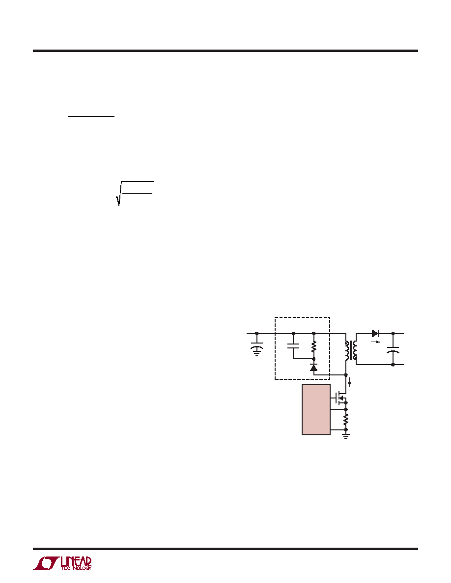
FLYBACK CONVERTER APPLICATIONS
TheLT3757canbeconfiguredasaflybackconverterforthe
applications where the converters have multiple outputs,
high output voltages or isolated outputs. Figure 7 shows
a simplified flyback converter.
The flyback converter has a very low parts count for mul-
tiple outputs, and with prudent selection of turns ratio, can
have high output/input voltage conversion ratios with a
desirable duty cycle. However, it has low efficiency due to
thehighpeakcurrents,highpeakvoltagesandconsequent
power loss. The flyback converter is commonly used for
an output power of less than 50W.
The flyback converter can be designed to operate either
in continuous or discontinuous mode. Compared to con-
tinuous mode, discontinuous mode has the advantage of
smaller transformer inductances and easy loop compen-
sation, and the disadvantage of higher peak-to-average
current and lower efficiency. In the high output voltage
applications, the flyback converters can be designed
to operate in discontinuous mode to avoid using large
transformers.
Figure 7. A Simplified Flyback Converter
RSENSE
NP:NS
VIN
CIN
CSN
VSN
LP
D
SUGGESTED
RCD SNUBBER
ID
ISW
VDS
3757 F06
GATE
GND
LT3757
SENSE
LS
M
+
–
+
–
RSN
DSN
–
+
COUT
+
相关PDF资料 |
PDF描述 |
|---|---|
| LM4040ESD-250GT3 | 1-OUTPUT TWO TERM VOLTAGE REFERENCE, 2.5 V, PDSO5 |
| LM4040DSD-330GT3 | 1-OUTPUT TWO TERM VOLTAGE REFERENCE, 3.3 V, PDSO5 |
| LM4040BIZ-5.0 | 1-OUTPUT TWO TERM VOLTAGE REFERENCE, 5 V, PBCY3 |
| LK5660-7EPD4TB1 | 2-OUTPUT 150 W AC-DC PWR FACTOR CORR MODULE |
| LT1374IR-5#TR | 8.5 A SWITCHING REGULATOR, 560 kHz SWITCHING FREQ-MAX, PSSO7 |
相关代理商/技术参数 |
参数描述 |
|---|---|
| LT3757MPMSE-TRPBF | 制造商:LINER 制造商全称:Linear Technology 功能描述:Boost, Flyback, SEPIC and Inverting Controller |
| LT3758 | 制造商:LINER 制造商全称:Linear Technology 功能描述:High Input Voltage, Boost, Flyback, SEPIC and Inverting Controller |
| LT3758A | 制造商:LINER 制造商全称:Linear Technology 功能描述:60V Low IQ Inverting DC/DC Controller Wide Operating VIN Range: 3.5V to 60V |
| LT3758AEDD#PBF | 制造商:Linear Technology 功能描述:IC REG CTRLR BST FLYBK INV 10DFN |
| LT3758AEDD#TRPBF | 制造商:Linear Technology 功能描述:IC REG CTRLR BST FLYBK INV 10DFN 制造商:Linear Technology 功能描述:SP-SWREG/Controller, High Input Voltage, Boost, Flyback, SEPIC and Inverting Con |
发布紧急采购,3分钟左右您将得到回复。