- 您现在的位置:买卖IC网 > PDF目录80057 > LTC3589IUJ-1#PBF (LINEAR TECHNOLOGY CORP) SWITCHING REGULATOR, 2600 kHz SWITCHING FREQ-MAX, PQCC40 PDF资料下载
参数资料
| 型号: | LTC3589IUJ-1#PBF |
| 厂商: | LINEAR TECHNOLOGY CORP |
| 元件分类: | 稳压器 |
| 英文描述: | SWITCHING REGULATOR, 2600 kHz SWITCHING FREQ-MAX, PQCC40 |
| 封装: | 6 X 6 MM, 0.75 MM HEIGHT, LEAD FREE, PLASTIC, QFN-40 |
| 文件页数: | 29/46页 |
| 文件大小: | 570K |
| 代理商: | LTC3589IUJ-1#PBF |
第1页第2页第3页第4页第5页第6页第7页第8页第9页第10页第11页第12页第13页第14页第15页第16页第17页第18页第19页第20页第21页第22页第23页第24页第25页第26页第27页第28页当前第29页第30页第31页第32页第33页第34页第35页第36页第37页第38页第39页第40页第41页第42页第43页第44页第45页第46页
LTC3589/LTC3589-1
35
3589fc
pulls down the SDA line during the write acknowledge
clock pulse so that it is a stable LOW during the HIGH
period of this clock pulse.
I2C Slave Address
The LTC3589/LTC3589-1 responds to factory programmed
read and write addresses. The write address is 0x68. The
read address is 0x69. The least significant bit of the address
byte, known as the read/write bit, is 0 when writing data
to the LTC3589/LTC3589-1 and 1 when reading from it.
I2C Sub-Addressed Writing
The LTC3589/LTC3589-1 has 14 command registers for
control inputs. They are accessed by the I2C port via a
sub-addressed writing system.
Each write cycle of the LTC3589/LTC3589-1 consists of a
series of three or more bytes beginning with the LTC3589/
LTC3589-1 write address. The second byte is the sub
address of the command register being written to. The
sub address is a pointer to the register where the data
in the third byte will be stored. The third byte is the data
to be written to the just-received sub address. Continue
alternating sub address and data bytes to write multiple
registers in a single START sequence.
I2C Bus Write Operation
The master initiates communication with the LTC3589/
LTC3589-1 with a START condition and the LTC3589/
LTC3589-1write address. If the address matches that of
the LTC3589/LTC3589-1, the LTC3589/LTC3589-1 returns
an acknowledge pulse. The master should then deliver the
sub address. Again the LTC3589/LTC3589-1 acknowledges
and the cycle is repeated for the data byte. The data byte
is transferred to an internal holding latch upon the return
of its acknowledge by the LTC3589/LTC3589-1. Continue
writing sub address and data pairs into the holding latches.
Addressing the LTC3589LTC3589-1 is not required for each
sub address and data pair. If desired a REPEAT-START
condition may be initiated by the master where another
device on the I2C bus is addressed. The LTC3589/LTC3589-1
remembers the valid data it has received. Once all the
devices on the I2C have been addressed and sent valid
data and a global STOP has been sent, the LTC3589/
LTC3589-1 will update its command latches with the data
it has received.
I2C Sub-Addressed Reading
The LTC3589/LTC3589-1 I2C interface supports random
address reading of the I2C command and status registers.
Before reading a register, the registers sub address must be
written. Send a START condition followed by the LTC3589/
LTC3589-1 write address followed by the sub address of
the register to be read. The sub address is now stored as
a pointer to the register. Send a REPEAT-START condition
followed by the LTC3589/LTC3589-1 read address. Follow-
ing the acknowledgment of its read address the LTC3589/
LTC3589-1 returns one bit of information for each of the
next 8 clock cycles. A STOP condition is not required for
the read operation. The read sub address is stored until
a new sub address is written.
Verify the data written to the internal data hold latches
prior to committing date to the command registers by
reading back the data before sending a STOP condition.
Continuously poll a register by repeatedly sending a
START condition followed by the LTC3589/LTC3589-1
read address, and then clocking the data out after the read
address acknowledge.
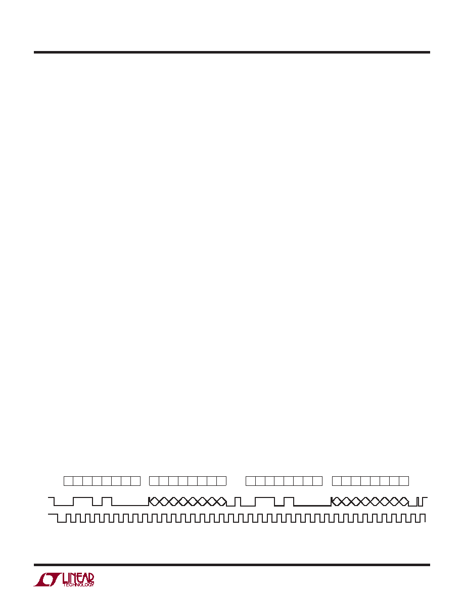
OPERATION
Figure 20. LTC3589 I2C Serial Port Read Pattern
ACK
START
STOP
1
0
23
11
ADDRESS
4
0
5678
000
9
123
45678
9
123
45678
011
01001
9
123
45678
9
1
01
1
0
10
0
WR
START
SDA
SCL
SUB ADDRESS
S7 S6
S3
S4
S5
S2
S1
S0
ADDRESS
01
1
0
10
0
RD
DATA
R7 R6
R3
R4
R5
R2 R1 R0
3589 F20
相关PDF资料 |
PDF描述 |
|---|---|
| LES015YJ38N | 1-OUTPUT 15 W DC-DC REG PWR SUPPLY MODULE |
| LES015ZH38N | 1-OUTPUT 15 W DC-DC REG PWR SUPPLY MODULE |
| LM2320-7ERV2F | 2-OUTPUT 50 W AC-DC REG PWR SUPPLY MODULE |
| LM2320-9ERD3A | 2-OUTPUT 50 W AC-DC REG PWR SUPPLY MODULE |
| LM2540-7ERD0AH | 2-OUTPUT 50 W AC-DC REG PWR SUPPLY MODULE |
相关代理商/技术参数 |
参数描述 |
|---|---|
| LTC3589IUJ-2#PBF | 功能描述:IC POWER MANAGEMENT RoHS:是 类别:集成电路 (IC) >> PMIC - 电源管理 - 专用 系列:* 标准包装:1 系列:- 应用:手持/移动设备 电流 - 电源:- 电源电压:3 V ~ 5.5 V 工作温度:-40°C ~ 85°C 安装类型:表面贴装 封装/外壳:14-WFDFN 裸露焊盘 供应商设备封装:14-LLP-EP(4x4) 包装:Digi-Reel® 配用:LP3905SD-30EV-ND - BOARD EVALUATION LP3905SD-30 其它名称:LP3905SD-30DKR |
| LTC3589IUJ-2#TRPBF | 功能描述:IC POWER MANAGEMENT RoHS:是 类别:集成电路 (IC) >> PMIC - 电源管理 - 专用 系列:* 标准包装:1 系列:- 应用:手持/移动设备 电流 - 电源:- 电源电压:3 V ~ 5.5 V 工作温度:-40°C ~ 85°C 安装类型:表面贴装 封装/外壳:14-WFDFN 裸露焊盘 供应商设备封装:14-LLP-EP(4x4) 包装:Digi-Reel® 配用:LP3905SD-30EV-ND - BOARD EVALUATION LP3905SD-30 其它名称:LP3905SD-30DKR |
| LTC3589IUJ-PBF | 制造商:LINER 制造商全称:Linear Technology 功能描述:8-Output Regulator with Sequencing and I2C |
| LTC3589IUJ-TRPBF | 制造商:LINER 制造商全称:Linear Technology 功能描述:8-Output Regulator with Sequencing and I2C |
| LTC3600EDD#PBF | 功能描述:IC REG BUCK SYNC ADJ 1.5A 12DFN RoHS:是 类别:集成电路 (IC) >> PMIC - 稳压器 - DC DC 开关稳压器 系列:- 标准包装:2,500 系列:- 类型:降压(降压) 输出类型:固定 输出数:1 输出电压:1.2V,1.5V,1.8V,2.5V 输入电压:2.7 V ~ 20 V PWM 型:- 频率 - 开关:- 电流 - 输出:50mA 同步整流器:是 工作温度:-40°C ~ 125°C 安装类型:表面贴装 封装/外壳:10-TFSOP,10-MSOP(0.118",3.00mm 宽)裸露焊盘 包装:带卷 (TR) 供应商设备封装:10-MSOP 裸露焊盘 |
发布紧急采购,3分钟左右您将得到回复。