- 您现在的位置:买卖IC网 > PDF目录15502 > LTC3732CG (Linear Technology)IC REG CTRLR BUCK PWM CM 36-SSOP PDF资料下载
参数资料
| 型号: | LTC3732CG |
| 厂商: | Linear Technology |
| 文件页数: | 18/28页 |
| 文件大小: | 0K |
| 描述: | IC REG CTRLR BUCK PWM CM 36-SSOP |
| 标准包装: | 37 |
| PWM 型: | 电流模式 |
| 输出数: | 1 |
| 频率 - 最大: | 750kHz |
| 占空比: | 98.5% |
| 电源电压: | 4.5 V ~ 7 V |
| 降压: | 是 |
| 升压: | 无 |
| 回扫: | 无 |
| 反相: | 无 |
| 倍增器: | 无 |
| 除法器: | 无 |
| Cuk: | 无 |
| 隔离: | 无 |
| 工作温度: | 0°C ~ 70°C |
| 封装/外壳: | 36-SSOP(0.209",5.30mm 宽) |
| 包装: | 管件 |
| 产品目录页面: | 1335 (CN2011-ZH PDF) |
第1页第2页第3页第4页第5页第6页第7页第8页第9页第10页第11页第12页第13页第14页第15页第16页第17页当前第18页第19页第20页第21页第22页第23页第24页第25页第26页第27页第28页
�� �
�
�LTC3732�
�APPLICATIO� S� I� FOR� ATIO�
�controller� is� permitted� to� start� operating.� As� the� voltage� on�
�RUN/SS� increases� from� 1.5V� to� 3.5V,� the� internal� current�
�limit� is� increased� from� 20mV/R� SENSE� to� 75mV/R� SENSE� .�
�The� output� current� limit� ramps� up� slowly,� taking� an�
�additional� 1s/� μ� F� to� reach� full� current.� The� output� current�
�thus� ramps� up� slowly,� eliminating� the� starting� surge�
�current� required� from� the� input� power� supply.� If� RUN/SS�
�has� been� pulled� all� the� way� to� ground,� there� is� a� delay�
�before� starting� of� approximately:�
�additional� time� before� latching� off:�
�t� LO2� >>� (C� SS� ?� 3V)/(1.5� μ� A)� =� 2� ?� 10� 6� (C� SS� )�
�This� built-in� overcurrent� latchoff� can� be� overridden� by�
�providing� a� pull-up� resistor� to� the� RUN/SS� pin� from� V� CC�
�as� shown� in� Figure� 7.� When� V� CC� is� 5V,� a� 200k� resistance�
�will� prevent� the� discharge� of� the� RUN/SS� capacitor�
�during� an� overcurrent� condition� but� also� shortens� the�
�soft-start� period,� so� a� larger� RUN/SS� capacitor� value� may�
�be� required.�
�(� )�
�=� 1� s� /� μ� F� C�
�1� .� 5� μ� A�
�(� )�
�=� 1� s� /� μ� F� C�
�1� .� 5� μ� A�
�t� DELAY� =�
�t� IRAMP� =�
�1� .� 5� V�
�C� SS� SS�
�3� V� ?� 1� .� 5� V�
�C� SS� SS�
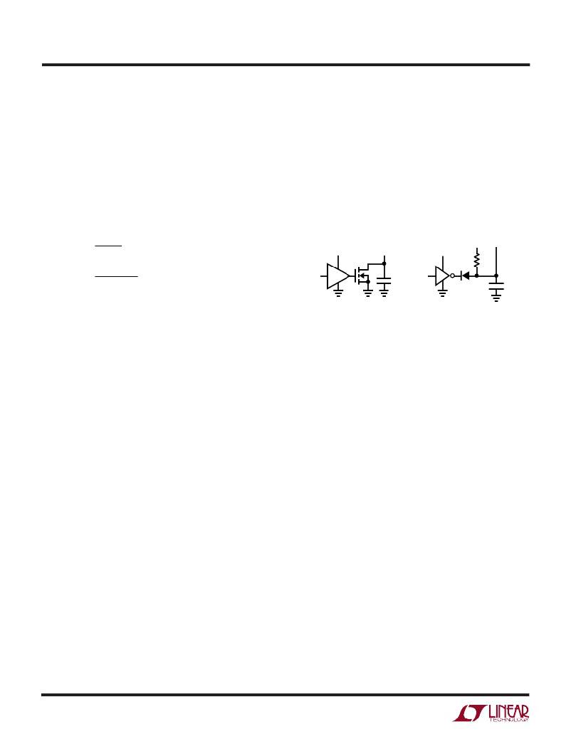
�SHDN�
�3.3V� OR� 5V�
�RUN/SS�
�PIN�
�C� SS�
�SHDN�
�5V�
�D1�
�RUN/SS�
�V� CC� PIN�
�R� SS�
�C� SS�
�3732� F07�
�By� pulling� the� RUN/SS� pin� below� 0.4V� the� IC� is� put� into� low�
�current� shutdown� (I� Q� <� 100� μ� A).� The� RUN/SS� pin� can� be�
�driven� directly� from� logic� as� shown� in� Figure7.� Diode,� D1,�
�in� Figure� 7� reduces� the� start� delay� but� allows� C� SS� to� ramp�
�up� slowly� providing� the� soft-start� function.� The� RUN/SS�
�pin� has� an� internal� 6V� zener� clamp� (see� the� Functional�
�Diagram).�
�Fault� Conditions:� Overcurrent� Latchoff�
�The� RUN/SS� pins� also� provide� the� ability� to� latch� off� the�
�controllers� when� an� overcurrent� condition� is� detected.� The�
�RUN/SS� capacitor� is� used� initially� to� turn� on� and� limit� the�
�inrush� current� of� all� three� output� stages.� After� the� control-�
�lers� have� been� started� and� been� given� adequate� time� to�
�charge� up� the� output� capacitor� and� provide� full� load�
�current,� the� RUN/SS� capacitor� is� used� for� a� short-circuit�
�timer.� If� the� output� voltage� falls� to� less� than� 70%� of� its�
�nominal� value,� the� RUN/SS� capacitor� begins� discharging�
�on� the� assumption� that� the� output� is� in� an� overcurrent�
�condition.� If� the� condition� lasts� for� a� long� enough� period,�
�as� determined� by� the� size� of� the� RUN/SS� capacitor,� the�
�discharge� current,� and� the� circuit� trip� point,� the� controller�
�will� be� shut� down� until� the� RUN/SS� pin� voltage� is� recycled.�
�If� the� overload� occurs� during� start-up,� the� time� can� be�
�approximated� by:�
�t� LO1� >>� (C� SS� ?� 0.6V)/(1.5� μ� A)� =� 4� ?� 10� 5� (C� SS� )�
�If� the� overload� occurs� after� start-up,� the� voltage� on� the�
�RUN/SS� capacitor� will� continue� charging� and� will� provide�
�Figure� 7.� RUN/SS� Pin� Interfacing�
�Why� should� you� defeat� overcurrent� latchoff?� During� the�
�prototyping� stage� of� a� design,� there� may� be� a� problem� with�
�noise� pick-up� or� poor� layout� causing� the� protection� circuit�
�to� latch� off� the� controller.� Defeating� this� feature� allows�
�troubleshooting� of� the� circuit� and� PC� layout.� The� internal�
�foldback� current� limiting� still� remains� active,� thereby�
�protecting� the� power� supply� system� from� failure.� A� deci-�
�sion� can� be� made� after� the� design� is� complete� whether� to�
�rely� solely� on� foldback� current� limiting� or� to� enable� the�
�latchoff� feature� by� removing� the� pull-up� resistor.�
�The� value� of� the� soft-start� capacitor� C� SS� may� need� to� be�
�scaled� with� output� current,� output� capacitance� and� load�
�current� characteristics.� The� minimum� soft-start� capaci-�
�tance� is� given� by:�
�C� SS� >� (C� OUT� )(V� OUT� )� (10� –4� )� (R� SENSE� )�
�The� minimum� recommended� soft-start� capacitor� of�
�C� SS� =� 0.1� μ� F� will� be� sufficient� for� most� applications.�
�Current� Foldback�
�In� certain� applications,� it� may� be� desirable� to� defeat� the�
�internal� current� foldback� function.� A� negative� impedance�
�is� experienced� when� powering� a� switching� regulator.�
�That� is,� the� input� current� is� higher� at� a� lower� V� IN� and�
�decreases� as� V� IN� is� increased.� Current� foldback� is� de-�
�signed� to� accommodate� a� normal,� resistive� load� having�
�3732f�
�18�
�相关PDF资料 |
PDF描述 |
|---|---|
| HBC26DRTF | CONN EDGECARD 52POS DIP .100 SLD |
| LTC1735CF#PBF | IC REG CTRLR BUCK PWM CM 20TSSOP |
| GBC60DRXS | CONN EDGECARD 120PS DIP .100 SLD |
| GSC22DRTN | CONN EDGECARD 44POS DIP .100 SLD |
| GMC22DRTN | CONN EDGECARD 44POS DIP .100 SLD |
相关代理商/技术参数 |
参数描述 |
|---|---|
| LTC3732CG#PBF | 功能描述:IC REG CTRLR BUCK PWM CM 36-SSOP RoHS:是 类别:集成电路 (IC) >> PMIC - 稳压器 - DC DC 切换控制器 系列:- 标准包装:2,000 系列:- PWM 型:电流模式 输出数:1 频率 - 最大:1MHz 占空比:50% 电源电压:9 V ~ 10 V 降压:无 升压:是 回扫:是 反相:无 倍增器:无 除法器:无 Cuk:无 隔离:无 工作温度:-40°C ~ 85°C 封装/外壳:8-TSSOP(0.173",4.40mm 宽) 包装:带卷 (TR) |
| LTC3732CG#TR | 功能描述:IC REG CTRLR BUCK PWM CM 36-SSOP RoHS:否 类别:集成电路 (IC) >> PMIC - 稳压器 - DC DC 切换控制器 系列:- 标准包装:4,500 系列:PowerWise® PWM 型:控制器 输出数:1 频率 - 最大:1MHz 占空比:95% 电源电压:2.8 V ~ 5.5 V 降压:是 升压:无 回扫:无 反相:无 倍增器:无 除法器:无 Cuk:无 隔离:无 工作温度:-40°C ~ 125°C 封装/外壳:6-WDFN 裸露焊盘 包装:带卷 (TR) 配用:LM1771EVAL-ND - BOARD EVALUATION LM1771 其它名称:LM1771SSDX |
| LTC3732CG#TRPBF | 功能描述:IC REG CTRLR BUCK PWM CM 36-SSOP RoHS:否 类别:集成电路 (IC) >> PMIC - 稳压器 - DC DC 切换控制器 系列:- 标准包装:4,500 系列:PowerWise® PWM 型:控制器 输出数:1 频率 - 最大:1MHz 占空比:95% 电源电压:2.8 V ~ 5.5 V 降压:是 升压:无 回扫:无 反相:无 倍增器:无 除法器:无 Cuk:无 隔离:无 工作温度:-40°C ~ 125°C 封装/外壳:6-WDFN 裸露焊盘 包装:带卷 (TR) 配用:LM1771EVAL-ND - BOARD EVALUATION LM1771 其它名称:LM1771SSDX |
| LTC3732CUHF | 功能描述:IC REG CTRLR BUCK PWM CM 38-QFN RoHS:否 类别:集成电路 (IC) >> PMIC - 稳压器 - DC DC 切换控制器 系列:- 标准包装:4,500 系列:PowerWise® PWM 型:控制器 输出数:1 频率 - 最大:1MHz 占空比:95% 电源电压:2.8 V ~ 5.5 V 降压:是 升压:无 回扫:无 反相:无 倍增器:无 除法器:无 Cuk:无 隔离:无 工作温度:-40°C ~ 125°C 封装/外壳:6-WDFN 裸露焊盘 包装:带卷 (TR) 配用:LM1771EVAL-ND - BOARD EVALUATION LM1771 其它名称:LM1771SSDX |
| LTC3732CUHF#PBF | 功能描述:IC REG CTRLR BUCK PWM CM 38-QFN RoHS:是 类别:集成电路 (IC) >> PMIC - 稳压器 - DC DC 切换控制器 系列:- 标准包装:4,500 系列:PowerWise® PWM 型:控制器 输出数:1 频率 - 最大:1MHz 占空比:95% 电源电压:2.8 V ~ 5.5 V 降压:是 升压:无 回扫:无 反相:无 倍增器:无 除法器:无 Cuk:无 隔离:无 工作温度:-40°C ~ 125°C 封装/外壳:6-WDFN 裸露焊盘 包装:带卷 (TR) 配用:LM1771EVAL-ND - BOARD EVALUATION LM1771 其它名称:LM1771SSDX |
发布紧急采购,3分钟左右您将得到回复。